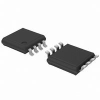
SA56004EDP,118 NXP Semiconductors, SA56004EDP,118 Datasheet - Page 22

SA56004EDP,118
Manufacturer Part Number
SA56004EDP,118
Description
IC TEMP SENSOR 8-TSSOP
Manufacturer
NXP Semiconductors
Datasheet
1.SA56004BDP118.pdf
(36 pages)
Specifications of SA56004EDP,118
Package / Case
8-TSSOP
Output Type
I²C™/SMBus™
Function
Temp Monitoring System (Sensor)
Topology
ADC (Sigma Delta), Multiplexer, Register Bank
Sensor Type
External & Internal
Sensing Temperature
-40°C ~ 125°C, External Sensor
Output Alarm
Yes
Output Fan
Yes
Voltage - Supply
3 V ~ 3.6 V
Operating Temperature
-40°C ~ 125°C
Mounting Type
Surface Mount
Supply Voltage (max)
5.5 V
Supply Voltage (min)
3 V
Maximum Operating Temperature
+ 125 C
Minimum Operating Temperature
- 40 C
Supply Current
1 mA
Lead Free Status / RoHS Status
Lead free / RoHS Compliant
For Use With
568-3615 - DEMO BOARD I2C
Lead Free Status / Rohs Status
Lead free / RoHS Compliant
Other names
568-3338-2
935274567118
SA56004EDP-T
935274567118
SA56004EDP-T
NXP Semiconductors
10. Characteristics
Table 18.
V
[1]
[2]
[3]
[4]
SA56004X_5
Product data sheet
Symbol
T
T
T
T
T
V
I
I
UVL
DD
RD
DD
ERRL
ERRR
RESR
RESL
conv
DD
= 3.0 V to 3.6 V; T
The SA56004X is optimized for 3.3 V V
Definition of Under Voltage Lockout (UVL): The value of V
minimum of 200 mV above the power-on reset. During the time that it is disabled, the temperature that is in the ‘read temperature
registers’ will remain at the value that it was before the A/D was disabled. This is done to eliminate the possibility of reading unexpected
false temperatures due to the A/D converter not working correctly due to low voltage. In case of power-up (rising V
is stored in the ‘read temperature registers’ will be the default value of 0 C. V
will function correctly and the normal temperature will be read.
V
V
DD
DD
(rising edge) voltage below which the A/D converter is disabled.
(falling edge) voltage below which the logic is reset.
Parameter
local temperature error
remote temperature error
remote temperature
resolution
local temperature resolution
conversion period
supply voltage
quiescent current
shut-down current
remote diode source current
UnderVoltage Lockout (UVL)
threshold voltage
Power-On Reset (POR)
threshold voltage
local and remote ALERT high
default temperature settings
local and remote ALERT low
default temperature settings
local and remote T_CRIT
default temperature settings
T_CRIT hysteresis
ALERT and T_CRIT output
saturation voltage
Electrical characteristics
amb
= 40 C to +125 C; unless otherwise specified.
[2]
DD
operation.
Conditions
T
T
T
T
T
T
during conversion,
16 Hz conversion rate
SMBus inactive
high setting: D+
low setting
V
conversion
V
default values set at power-up
default values set at power-up
default values set at power-up
default value set at power-up
I
O
amb
amb
amb
RD
amb
RD
DD
DD
= 6.0 mA
= +60 C to +100 C
= 40 C to +125 C
input disables A/D
input falling edge
= +60 C to +100 C
= 40 C to +125 C
= +25 C to +85 C;
= 40 C to +85 C;
Rev. 05 — 22 May 2008
DD
Digital temperature sensor with overtemperature alarms
below which the internal A/D converter is disabled. This is designed to be a
D = +0.65 V
DD
will rise to the value of the UVL, at which point the A/D
[1]
[3]
[4]
Min
-
-
-
-
-
3.0
-
-
-
-
2.6
1.8
-
-
-
-
-
2
3
1
3
Typ
-
-
-
11
0.125
11
0.125
38
-
500
10
160
10
-
-
+70
0
+85
+10
-
1
SA56004X
© NXP B.V. 2008. All rights reserved.
Max
+2
+3
+1
+3
-
-
-
-
-
5.5
-
-
-
-
2.95
2.4
-
-
-
-
0.4
DD
), the reading that
22 of 36
Unit
bit
bit
ms
V
V
V
V
C
C
C
C
C
C
C
C
C
C
A
A
A
A


