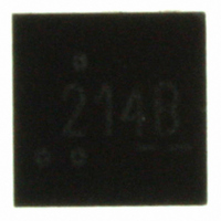
FPF2214 Fairchild Semiconductor, FPF2214 Datasheet - Page 10

FPF2214
Manufacturer Part Number
FPF2214
Description
IC LOAD SWITCH MICROFET6
Manufacturer
Fairchild Semiconductor
Type
High Side Switchr
Datasheet
1.FPF2213.pdf
(14 pages)
Specifications of FPF2214
Number Of Outputs
1
Rds (on)
325 mOhm
Internal Switch(s)
Yes
Current Limit
Adjustable
Voltage - Input
1.8 ~ 5.5 V
Operating Temperature
-40°C ~ 85°C
Mounting Type
Surface Mount
Package / Case
6-MLP, 6-MicroFET™
Input Voltage
1.8 to 5.5V
Power Switch On Resistance
350mOhm
Output Current
250mA
Mounting
Surface Mount
Package Type
MicroFET
Operating Temperature (min)
-40C
Operating Temperature (max)
85C
Operating Temperature Classification
Industrial
Pin Count
6
Power Dissipation
1.2W
Lead Free Status / RoHS Status
Lead free / RoHS Compliant
Other names
FPF2214TR
Available stocks
Company
Part Number
Manufacturer
Quantity
Price
Company:
Part Number:
FPF2214
Manufacturer:
Fairchild Semiconductor
Quantity:
135
FPF2213-FPF2215 Rev. C
Application Information
Setting Current Limit
The FPF2213, FPF2214, and FPF2215 have adjustable high
precision current limit which is set with an external resistor
connected between ISET and GND. Please see the layout
recommendation section of the application note for the
recommended R
using the following equation:
For a particular I
below formula:
FPF221X family has 5% precision at higher load current. The
I
using Figure 21 (I
The table and figure below can be used to select R
LIM (Max)
I
R
LIM (Typ)
Tolerance (%) = 100 *
I
R
LIM (Max)
26.8
28.0
29.4
30.0
32.4
36.5
40.2
48.7
60.0
SET
[k ]
SET
(K ) =
and tolerance of current limit value can be determined
(mA) =
Min. Current
= I
Limit [mA]
250
238
226
221
204
179
160
129
100
LIM (Typ) +
I
LIM (Min)
SET
Table 1: R
LIM
LIM
R
(min) value, R
layout. The R
SET
vs R
7050
(mA) + 10 +
(K )
SET
Typ. Current
I
SET
LIM (Typ)
Limit [mA]
7050
I
) and the following formula:
263
252
240
235
218
193
175
145
118
LIM (Typ)
Selection Guide
SET
I
SET
LIM (Typ)
* Tolerance (%)
100
I
- I
resistance is selected by
LIM (Min)
can be calculated from
LIM (Min)
Max. Current
Limit [mA]
750
276
265
253
249
232
208
190
161
135
(mA)
SET
:
11.1
15.0
[%]
Tol
5.0
5.4
5.7
5.8
6.4
7.5
8.5
10
Input Capacitor
To limit the voltage drop on the input supply caused by transient
in-rush currents when the switch is turned on into a discharged
load capacitor or a short-circuit, a capacitor is recommended to
be placed between V
placed close to the pins is usually sufficient. Higher values of
C
Output Capacitor
A 0.1uF capacitor C
GND. This capacitor will prevent parasitic board inductances
from forcing V
FPF2213 and FPF2214, the total output capacitance needs to
be kept below a maximum value, C
part from registering an over-current condition and turning-off
the switch. The maximum output capacitance can be
determined from the following formula:
Power Dissipation
During normal on-state operation, the power dissipated in the
device will depend upon the level at which the current limit is
set. The maximum allowed setting for the current limit is 250mA
and will result in a power dissipation of:
If the part goes into current limit, maximum power dissipation
will occur when the output is shorted to ground. For the
FPF2213, the power dissipation will be scaled by the Auto-
Restart Time, t
t
BLANK
IN
305
275
245
215
185
155
125
can be used to further reduce the voltage drop.
95
P
26
. Therefore, the maximum power dissipated is:
(Max)
C
P = (I
OUT (Max)
=
=
OUT
LIM
32
RSTRT
t
BLANK
30 + 450
)
2
below GND when the switch turns-off. For the
=
* R
Figure 21. I
30
OUT
t
IN
BLANK
, and the Over Current Blanking Time,
DS
+ t
and GND. A 1uF ceramic capacitor, C
, should be placed between V
38
I
RSTRT
= (0.25)
LIM (Max)
R
* 5.5 * 0.276 = 94mW
SET
LIM
(KOhms)
2
44
* t
V
vs R
* 0.275 = 17mW
* V
IN
BLANK (Min)
OUT
IN (Max)
SET
(max), to prevent the
50
* I
LIM (Max)
www.fairchildsemi.com
56
OUT
Max
Typ
Min
and
IN
62
,


