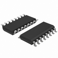
TEA1751LT/N1,518 NXP Semiconductors, TEA1751LT/N1,518 Datasheet - Page 23

TEA1751LT/N1,518
Manufacturer Part Number
TEA1751LT/N1,518
Description
IC CTRLR GREENCHIP SMPS 16-SOIC
Manufacturer
NXP Semiconductors
Series
GreenChip™ IIIr
Datasheet
1.TEA1751LTN1518.pdf
(29 pages)
Specifications of TEA1751LT/N1,518
Package / Case
16-SOIC (3.9mm Width)
Mode
Continuous Conduction (CCM)
Frequency - Switching
125kHz
Current - Startup
60µA
Voltage - Supply
0.65 V ~ 22 V
Operating Temperature
-20°C ~ 150°C
Mounting Type
Surface Mount
Output Voltage
11 V
Output Current
- 1.19 mA
Input Voltage
70 V to 276 V
Switching Frequency
125 KHz
Mounting Style
SMD/SMT
Supply Current
3 mA
Lead Free Status / RoHS Status
Lead free / RoHS Compliant
Lead Free Status / RoHS Status
Lead free / RoHS Compliant, Lead free / RoHS Compliant
Other names
568-4925-2
935286559518
TEA1751LT/N1,518
935286559518
TEA1751LT/N1,518
NXP Semiconductors
Table 5.
T
the IC; unless otherwise specified.
TEA1751T_LT_2
Product data sheet
Symbol
I
V
Overvoltage protection flyback (pin FBAUX)
I
N
Demagnetization management flyback (pin FBAUX)
V
I
V
t
Pulse width modulator flyback
t
t
Oscillator flyback
f
V
V
ΔV
Peak current control flyback (pin FBCTRL)
V
V
R
I
I
Valley switching flyback (pin HV)
(ΔV/Δt)
sink(PFCDRIVER)
ovp(FBAUX)
prot(FBAUX)
sup(xfmr_ring)
on(fb)min
on(fb)max
sw(fb)max
O(FBCTRL)
to(FBCTRL)
amb
O(PFCDRIVER)max
th(comp)FBAUX
clamp(FBAUX)
start(VCO)FBCTRL
hys(FBCTRL)
FBCTRL
to(FBCTRL)
cy(ovp)
int(FBCTRL)
VCO(FBCTRL)
= 25
vrec(fb)
°
C; V
Characteristics
CC
= 20 V; all voltages are measured with respect to ground (pin 2); currents are positive when flowing into
Parameter
sink current on pin
PFCDRIVER
maximum output voltage on pin
PFCDRIVER
overvoltage protection current
on pin FBAUX
number of overvoltage
protection cycles
comparator threshold voltage
on pin FBAUX
protection current on pin
FBAUX
clamp voltage on pin FBAUX
transformer ringing
suppression time
minimum flyback on-time
maximum flyback on-time
maximum flyback switching
frequency
VCO start voltage on pin
FBCTRL
hysteresis voltage on pin
FBCTRL
VCO voltage difference on pin
FBCTRL
voltage on pin FBCTRL
time-out voltage on pin
FBCTRL
internal resistance on pin
FBCTRL
output current on pin FBCTRL
time-out current on pin
FBCTRL
flyback valley recognition
voltage change with time
…continued
Rev. 02 — 23 December 2009
Conditions
V
V
V
I
I
for maximum flyback peak current
enable voltage
trip voltage
V
V
V
V
FBAUX
FBAUX
PFCDRIVER
PFCDRIVER
FBAUX
FBCTRL
FBCTRL
FBCTRL
FBCTRL
= −500 μA
= 500 μA
= 50 mV
= 0 V
= 2 V
= 2.6 V
= 4.1 V
= 2 V
= 10 V
TEA1751T; TEA1751LT
[4]
GreenChip III SMPS control IC
Min
-
-
-
279
6
60
−50
−1.0
0.5
1.5
-
32
100
1.3
-
-
1.85
-
4.2
-
−1.4
−0.6
−36
−34.5 −28.5 −22.5 μA
−75
Typ
0.7
11
300
8
80
-
−0.8
0.7
2
t
40
125
1.5
60
-0.1
2.0
2.5
3
−1.19 −0.93 mA
−0.5
−30
-
1.2
4.5
leb
© NXP B.V. 2009. All rights reserved.
Max
-
-
12
321
12
110
−5
−0.6
0.9
2.5
-
48
150
1.7
-
-
2.15
-
4.8
-
−0.4
−24
+75
Unit
A
A
V
μA
mV
nA
V
V
μs
ns
μs
kHz
V
mV
V
V
V
V
kΩ
mA
μA
V/μs
23 of 29


