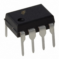
FAN7527BN Fairchild Semiconductor, FAN7527BN Datasheet - Page 5

FAN7527BN
Manufacturer Part Number
FAN7527BN
Description
IC PFC CTRLR TRANSITION 8DIP
Manufacturer
Fairchild Semiconductor
Datasheet
1.FAN7527BMX.pdf
(12 pages)
Specifications of FAN7527BN
Mode
Discontinuous (Transition)
Current - Startup
60µA
Voltage - Supply
11.5 V ~ 30 V
Operating Temperature
-25°C ~ 125°C
Mounting Type
Through Hole
Package / Case
8-DIP (0.300", 7.62mm)
Maximum Power Dissipation
0.8 W
Maximum Operating Temperature
+ 125 C
Mounting Style
Through Hole
Minimum Operating Temperature
- 25 C
Startup Current
60µA
Operating Supply Current
3mA
Digital Ic Case Style
DIP
No. Of Pins
8
Operating Temperature Range
-25°C To +125°C
Leaded Process Compatible
Yes
Peak Reflow Compatible (260 C)
Yes
Rohs Compliant
Yes
Uvlo
3V
Lead Free Status / RoHS Status
Lead free / RoHS Compliant
Frequency - Switching
-
Lead Free Status / Rohs Status
Lead free / RoHS Compliant
Other names
FAN7527BN_NL
FAN7527BN_NL
FAN7527BN_NL
Available stocks
Company
Part Number
Manufacturer
Quantity
Price
Part Number:
FAN7527BN
Manufacturer:
FAIRCHILD/仙童
Quantity:
20 000
Electrical Characteristics
V
Characteristics
< UNDER VOLTAGE LOCKOUT SECTION>
Start threshold voltage
UVLO hysteresis
< SUPPLY CURRENT SECTION >
Start-up supply current
Operating supply current
Operating current at OVP
Dynamic operating supply current
< ERROR AMPLIFIER SECTION >
Voltage feedback input threshold
Line regulation
Temperature stability of Vref (Note1)
Input bias current
Output source current
Output sink current
Output upper clamp voltage (Note2)
Output lower clamp voltage (Note3)
Large signal open loop gain (Note4)
Power supply rejection ratio (Note5)
Unity gain bandwidth (Note6)
Slew rate (Note7)
< MULTIPLIER SECTION>
Input bias current (pin3)
M1 input voltage range (pin3)
M2 input voltage range (pin2)
Multiplier gain (Note8)
Maximum multiplier output voltage
Temperature stability of K (Note9)
CC
= 14V, -25 C
Ta
125 C, unless otherwise stated.
Vomax(m) Vinv =0V, Vm1 = 4V
Veao(H)
Symbol
Veao(L)
I
I
PSRR
V
cc(ovp)
HY(st)
Ib
source
GBW
Ib
Isink
V
I
V
V
K/ T
th(st)
SR
V
V
G
I
dcc
I
(ea)
cc
K
(m)
st
ref
ref
ref
m
m
v
1
2
1
3
Vcc Increasing
Vcc = Vth(st) -0.2V
Output not switching
Vinv = 3V
50kHz, CI = 1nF
Iref = 0mA, Ta = 25 C
-25
14V
-25
Vm2 = 4V
Vm2 = 4V
Isource = 0.1mA
Isink = 0.1mA
14V
Vm1 = 1V, Vm2 = 3.5V
-25
Test Condition
Ta
Ta
Ta
Vcc
Vcc
125 C
125 C
125 C
25V
25V
-
-
-
-
-
-
-
-
2.465
Min.
10.5
2.44
0.36
1.65
-0.5
-0.5
Vref
10
60
60
-2
2
2
0
-
-
-
-
-
-
-
-
-
-
Typ.
2.25
11.5
0.44
-0.2
1.7
2.5
2.5
0.1
0.6
1.8
60
20
80
80
-4
3
3
4
4
6
1
-
-
-
-
Vref+2.5
2.535
Max.
12.5
2.56
0.52
1.95
100
0.5
0.5
3.8
10
4
6
4
8
-
-
-
-
-
-
-
-
-
-
FAN7527B
%/ C
MHz
Unit
V/us
mA
mA
mA
mV
mV
mA
mA
1/V
uA
uA
dB
dB
uA
V
V
V
V
V
V
V
V
V
5


