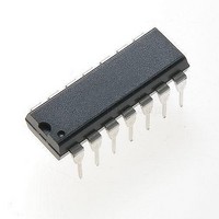
FAN8100N Fairchild Semiconductor, FAN8100N Datasheet

FAN8100N
Specifications of FAN8100N
Available stocks
Related parts for FAN8100N
FAN8100N Summary of contents
Page 1
... Precision instruments ©2005 Fairchild Semiconductor Corporation www.fairchildsemi.com Description The FAN8100N/FAN8100MTC is a monolithic two channel dc motor drive IC designed for low voltage operated sys- tems. It has dual H-bridge drivers, using NPN and vertical- PNP power transistors with a low saturation voltage. Power packages with heat sinks endure high continuous output cur- rent ...
Page 2
... FAN8100N/FAN8100MTC Pin Assignments FIN FAN8100N FIN Pin Definitions Pin Number Pin Name 1(12) REVERSEB 2(13) FORWARDB 3(14) OUT2B FIN(1) GND 4(2) OUT1B 5(3) PVCCB 6(4) VCC 7(5) D1A 8(6) PVCCA 9(7) OUT1A FIN(8) GND 10(9) OUT2A 11(10) FORWARDA 12(11) REVERSEA Note FAN8100MTC ...
Page 3
... Internal Block Diagram FORWARDA 11 REVERSEA 12 FORWARDB 2 REVERSEB 1 VCC 6 Ch. A Control Circuit Bias & TSD Circuit Ch. B Control Circuit Fin GND Note: FAN8100N pin number FAN8100N/FAN8100MTC D1A 7 PVCCA 8 OUT1A 9 OUT2A 10 PVCCB 5 OUT1B 4 OUT2B 3 3 ...
Page 4
... FAN8100N/FAN8100MTC Absolute Maximum Ratings ( Parameter Maximum logic and control supply voltage Maximum output supply voltage Maximum output applied voltage Maximum applied input voltage Maximum D1A Voltage Peak output current per channel Note FAN8100MTC Recommended Operating Conditions ( Parameter Logic and control circuit supply voltage ...
Page 5
... SOA 100 Ambient temperature 1.0 0.5 SOA 100 Ambient temperature 114mm 1.57mm PCB (FR-4 glass epoxy material). and C (FAN8100N) 32mW/ (FAN8100MTC) for using above Ta=25 FAN8100N/FAN8100MTC Value Unit 2.0 FAN8100N: W FAN8100MTC: 1 125 C 150 C 150 125 150 175 125 150 175 ...
Page 6
... FAN8100N/FAN8100MTC Electrical Characteristics (Ta=25 C, VCC=3V, PVCCA=PVCCB=3V, unless otherwise specified) Parameter Stand-by current ( VCC PVCCA PVCCB VCC supply current VCC VCC supply current VCC Total supply current VCC PVCCA PVCCB Total supply current VCC PVCCA PVCCB Saturation voltage 1 (upper + lower output transistors total) ...
Page 7
... A TURBO Output Voltage OUT1 OUT Notes: **See typical application circuits. OUT1A OUT2A OUT1B OUT2B High impedance FAN8100N/FAN8100MTC Function Stand-by (Stop) Forward Reverse Brake Function Stand-by (Stop) Forward Reverse Brake **Should be 'L' H **Should be ' **when an external turbo circuit is used time 7 ...
Page 8
... Making the wiring lines thick and short, especially between power supply (PVCC) and GND. • Putting a passthrough capacitor near the IC The R of the FAN8100N/MTC can be reduced by soldering the GND pins to a suitable copper area of the printed circuit th-ja board as shown in following figure recommended the copper area is as large as possible. ...
Page 9
... Typical Application Circuits 1. RF Remote Controlled Car RF Signal 16 RF Circuits (Discrete Parts Remote Controlled Car with a Turbo Function RF Signal 16 RF Circuits (Discrete Parts Receiver Controller FAN8100N/FAN8100MTC RX Receiver Controller FAN8100N/FAN8100MTC RX FAN8100N/FAN8100MTC FORWARD BACKWARD 10 FIN FIN RIGHT LEFT Q1 FORWARD BACKWARD 10 FIN FIN RIGHT LEFT 9 ...
Page 10
... FAN8100N/FAN8100MTC Typical Performance Characteristics (FAN8100N) 6 Brake 5 4 Forward / Reverse - Ambient Temperature Ta [℃ Brake 40 Forward / Reverse - Ambient Temperature Ta [℃ -40 - Ambient Temperature Ta [℃] 10 VCC = PVCC = 100 150 0 0.1 VCC = PVCC = 3V 180 160 140 120 100 100 150 0 VCC = PVCC = VIN = 100 120 0 60 ...
Page 11
... VCC = PVCC = VIN = 100 120 FAN8100N/FAN8100MTC 0.1 0.2 0.3 0.4 0.5 0 0.8 Output Current IO [℃] VCC = PVCC = Input Voltage VIN [V] VCC = PVCC = 3V Brake Forward / Reverse Supply Voltage VCC [V] VCC = PVCC = 3V Brake Forward / Reverse Supply Voltage PVCC [V] 0.9 1 ...
Page 12
... FAN8100N/FAN8100MTC Mechanical Dimensions (Unit: mm) Package Dimension 12 12-DIPH-300 ...
Page 13
... Mechanical Dimensions (Unit: mm) Package dimensions (Continued) 14-TSSOP FAN8100N/FAN8100MTC 13 ...
Page 14
... FAN8100N/FAN8100MTC DISCLAIMER FAIRCHILD SEMICONDUCTOR RESERVES THE RIGHT TO MAKE CHANGES WITHOUT FURTHER NOTICE TO ANY PRODUCTS HEREIN TO IMPROVE RELIABILITY, FUNCTION OR DESIGN. FAIRCHILD DOES NOT ASSUME ANY LIABILITY ARISING OUT OF THE APPLICATION OR USE OF ANY PRODUCT OR CIRCUIT DESCRIBED HEREIN; NEITHER DOES IT CONVEY ANY LICENSE UNDER ITS PATENT RIGHTS, NOR THE RIGHTS OF OTHERS. ...


