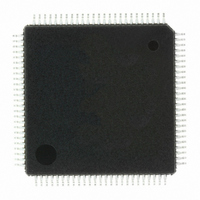
IRMCF312TR International Rectifier, IRMCF312TR Datasheet - Page 2

IRMCF312TR
Manufacturer Part Number
IRMCF312TR
Description
IC MOTOR CTRL RAM 2CH 100-QFP
Manufacturer
International Rectifier
Datasheet
1.IRMCF312TR.pdf
(35 pages)
Specifications of IRMCF312TR
Applications
AC Motor Controller, Permanent Magnet
Number Of Outputs
2
Voltage - Supply
3 V ~ 3.6 V
Operating Temperature
-40°C ~ 85°C
Mounting Type
Surface Mount
Package / Case
100-LQFP
Motion Control Description
Dual Channel Sensorless PM Motor Control IC
Package
QFP100
Moisture Sensitivity Level
MSL3
Lead Free Status / RoHS Status
Lead free / RoHS Compliant
Current - Output
-
Voltage - Load
-
Available stocks
Company
Part Number
Manufacturer
Quantity
Price
Company:
Part Number:
IRMCF312TR
Manufacturer:
International Rectifier
Quantity:
10 000
1
2
3
4
5
6
7
8
9
10
4.1
4.2
4.3
4.4
4.5
6.1
6.2
6.3
6.4
6.5
6.6
6.7
6.8
7.1
7.2
7.3
7.4
7.5
7.6
7.7
7.8
7.9
7.10
7.11
7.12
Overview...................................................................................................................................... 4
IRMCF312 Block Diagram and Main Functions ........................................................................ 5
Pinout........................................................................................................................................... 7
Input/Output of IRMCF312......................................................................................................... 8
Application Connections ........................................................................................................... 13
DC Characteristics ..................................................................................................................... 14
AC Characteristics ..................................................................................................................... 19
7.9.1
7.9.2
Pin List....................................................................................................................................... 30
Package Dimensions.................................................................................................................. 34
Part Marking Information....................................................................................................... 35
8051 Peripheral Interface Group........................................................................................... 9
Motion Peripheral Interface Group ..................................................................................... 10
Analog Interface Group ...................................................................................................... 11
Power Interface Group ........................................................................................................ 12
Test Interface....................................................................................................................... 12
Absolute Maximum Ratings ............................................................................................... 14
System Clock Frequency and Power Consumption............................................................ 14
Digital I/O DC Characteristics............................................................................................ 15
PLL and Oscillator DC Characteristics............................................................................... 16
Analog I/O DC Characteristics ........................................................................................... 16
Analog I/O DC Characteristics ........................................................................................... 17
Under Voltage Lockout DC Characteristics ....................................................................... 18
CMEXT and AREF Characteristics.................................................................................... 18
PLL AC Characteristics ...................................................................................................... 19
Analog to Digital Converter AC Characteristics ................................................................ 20
Op Amp AC Characteristics ............................................................................................... 21
Op Amp AC Characteristics ............................................................................................... 21
SYNC to SVPWM and A/D Conversion AC Timing......................................................... 22
GATEKILL to SVPWM AC Timing.................................................................................. 23
Interrupt AC Timing ........................................................................................................... 23
I
SPI AC Timing.................................................................................................................... 25
2
C AC Timing .................................................................................................................... 24
UART AC Timing ........................................................................................................... 27
CAPTURE Input AC Timing .......................................................................................... 28
JTAG AC Timing ............................................................................................................ 29
SPI Write AC timing .................................................................................................... 25
SPI Read AC Timing.................................................................................................... 26
TABLE OF CONTENTS
IRMCF312
2


