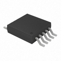
TC654EUN Microchip Technology, TC654EUN Datasheet - Page 10

TC654EUN
Manufacturer Part Number
TC654EUN
Description
IC PWM FAN SPEED CTRLR 10-MSOP
Manufacturer
Microchip Technology
Type
High Speed PWM Controllerr
Datasheet
1.TC654EUN.pdf
(36 pages)
Specifications of TC654EUN
Number Of Outputs
1
Package / Case
10-MSOP, Micro10™, 10-uMAX, 10-uSOP
Applications
Fan Controller, Brushless (BLDC)
Voltage - Supply
3 V ~ 5.5 V
Operating Temperature
-40°C ~ 85°C
Mounting Type
Surface Mount
Output Current
5 mA (Min)
Operating Supply Voltage
3 V to 5.5 V
Maximum Operating Temperature
+ 85 C
Minimum Operating Temperature
- 40 C
Mounting Style
SMD/SMT
Motor Type
PWM
No. Of Outputs
1
Output Voltage
4.4V
Supply Voltage Range
3V To 5.5V
Driver Case Style
MSOP
No. Of Pins
10
Operating Temperature Range
-40°C To +85°C
Rohs Compliant
Yes
Lead Free Status / RoHS Status
Lead free / RoHS Compliant
Current - Output
-
Voltage - Load
-
Lead Free Status / Rohs Status
Lead free / RoHS Compliant
Available stocks
Company
Part Number
Manufacturer
Quantity
Price
Part Number:
TC654EUN
Manufacturer:
MIC
Quantity:
20 000
Part Number:
TC654EUNTR
Manufacturer:
MICROCHIP/微芯
Quantity:
20 000
TC654/TC655
4.1
The speed of a DC brushless fan is proportional to the
voltage across it. For example, if a fan’s rating is
5000 RPM at 12 V, it’s speed would be 2500 RPM at
6 V. This, of course, will not be exact, but should be
close.
There are two main methods for fan speed control. The
first is pulse width modulation (PWM) and the second
is linear. Using either method the total system power
requirement to run the fan is equal. The difference
between the two methods is where the power is
consumed.
The following example compares the two methods for
a 12 V, 120 mA fan running at 50% speed. With 6 V
applied across the fan, the fan draws an average cur-
rent of 68 mA. Using a linear control method, there is
6V across the fan and 6V across the drive element.
With 6 V and 68 mA, the drive element is dissipating
410 mW of power. Using the PWM approach, the fan is
modulated at a 50% duty cycle, with most of the 12 V
being dropped across the fan. With 50% duty cycle, the
fan draws an RMS current of 110 mA and an average
current of 72 mA. Using a MOSFET with a 1
(a fairly typical value for this low current) the power dis-
sipation in the drive element would be: 12 mW (Irms
RDS
(assuming a Vce-sat of 0.8 V), the power dissipation
would be 58 mW (Iavg* Vce-sat).
The PWM approach to fan speed control causes much
less power dissipation in the drive element. This allows
smaller devices to be used and will not require any spe-
cial heatsinking to get rid of the power being dissipated
in the package.
The other advantage to the PWM approach is that the
voltage being applied to the fan is always near 12 V.
This eliminates any concern about not supplying a high
enough voltage to run the internal fan components
which is very relevant in linear fan speed control.
4.2
The TC654 and TC655 devices implement PWM fan
speed control by varying the duty cycle of a fixed fre-
quency pulse train. The duty cycle of a waveform is the
on time divided by the total period of the pulse. For
example, given a 100 Hz waveform (10 msec.) with an
on time of 5.0 msec, the duty cycle of this waveform is
50% (5.0 msec/10.0 msec). An example of this is
illustrated in Figure 4-2.
DS21734A-page 10
(on)
). Using a standard 2N2222A NPN transistor
Fan Speed Control Methods
PWM Fan Speed Control
RDS
(on)
2
*
FIGURE 4-2:
Waveform.
The TC654 and TC655 generate a pulse train with a
typical frequency of 30 Hz (C
can be varied from 30% to 100%. The pulse train gen-
erated by the TC654/TC655 devices drives the gate of
an external N-channel MOSFET or the base of an NPN
transistor (Figure 4-3). See Section 7.5 for more
information on output drive device selection.
FIGURE 4-3:
By modulating the voltage applied to the gate of the
MOSFET Qdrive, the voltage applied to the fan is also
modulated. When the V
the MOSFET is turned on, pulling the voltage at the
drain of Qdrive to 0 V. This places the full 12 V across
the fan for the Ton period of the pulse. When the duty
cycle of the drive pulse is 100% (full on, Ton = T), the
fan will run at full speed. As the duty cycle is decreased
(pulse on time “Ton” is lowered), the fan will slow down
proportionally. With the TC654 and TC655 devices, the
duty cycle can be controlled through the analog input
pin (V
Duty-Cycle Register. See Section 4.5 for more details
on duty cycle control.
IN
TC654/
TC655
) or through the SMBus interface by using the
D = Duty Cycle
D = Ton / T
Ton
V
V
DD
T
OUT
GND
Toff
Duty Cycle Of A PWM
PWM Fan Drive.
OUT
2002 Microchip Technology Inc.
pulse is high, the gate of
F
T = Period
T = 1/F
F = Frequency
= 1 µF). The duty cycle
G
12 V
FAN
D
S
Qdrive


