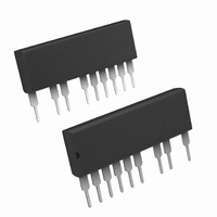
IR3101 International Rectifier, IR3101 Datasheet

IR3101
Specifications of IR3101
Related parts for IR3101
IR3101 Summary of contents
Page 1
... Integrated Driver Description IR3101 is a gate driver IC integrated half bridge FredFET designed for sub 250W (heat-sink-less) motor drive applications. The sleek and compact single-in-line package is optimized for electronic motor control in appliance applications such as fans and compressors for refrigerators. The IR3101 offers an extremely compact, high performance half-bridge inverter single isolated package for a very simple design for two- phase and three-phase motor drivers ...
Page 2
... IR3101 Internal Electrical Schematic - IR3101 Figure 1: Internal connections Recommended Operating Conditions For proper operation, the device should be used within the recommended conditions. Symbol Definition V High side floating supply absolute voltage B V High voltage supply DD V Low side and logic fixed supply voltage ...
Page 3
... RR C Output capacitance oss www.irf.com o C unless otherwise specified. The V Min. Typ 500 - - - - 0.8 - 0.82 - 1.7 - 0.70 - 100 - 105 - 150 - 130 - - IR3101 parameter is referenced to COM. DD Max. Units Conditions - V V =0V, I =250 =500V 1. 1.5A 1.5A, T =125° 0. 1.5A, V ...
Page 4
... IR3101 Driver IC Characteristic Symbol Definition V supply undervoltage CC V CCUV+ positive going threshold V supply undervoltage CC V CCUV- negative going threshold V supply undervoltage CC V CCUVH lockout hysteresis V supply undervoltage BS V BSUV+ positive going threshold V supply undervoltage BS V BSUV- negative going threshold V supply undervoltage ...
Page 5
... Logic and internal gate drive supply Logic input for high side gate output Logic input for low side gate output Not Connected Logic Ground Low side MOSFET gate return Not Connected High side gate drive floating supply Half bridge output Not Connected High voltage supply IR3101 5 ...
Page 6
... IR3101 Typical Application Connection IR3101 V + BUS V V IR3101 B BUS Driver COM V - BUS 1. Electrolytic bus capacitors should be mounted as close to the module bus terminals as possible to re- duce ringing and EMI problems. Additional high frequency ceramic capacitor mounted close to the module pins will further improve performance. ...
Page 7
... Trapezoidal modulation, 120° switching,V T =100°C, T =125° www.irf.com Switching Frequency [kHz] =300V, Duty Cycle=0.8, without heatsink: BUS Switching Frequency [kHz] =300V, Duty Cycle=0.8, with heatsink: BUS IR3101 Low Side MOSFET High Side MOSFET Low Side MOSFET High Side MOSFET ...
Page 8
... IR3101 9.75 8.75 7.75 6.75 5.75 4.75 3.75 2.75 1.75 0.75 -0.25 0.2 0.3 Figure 5. FredFET Turn-on. Typical turn-on waveform @T 2.25 1.75 1.25 0.75 0.25 -0.25 0 0.1 0.2 Figure 6. FredFET Turn-off. Typical turn-on waveform @T 8 0.4 0.5 0.6 Time ( s) 0.3 0.4 ...
Page 9
... Figure 7: Normalized On-Resistance vs temperature V =10V, I = 6.8 7.5 4.7 5 3.3 2 Figure 8: Recommended minimum Bootstrap Capacitor value vs Switching Frequency Figure 8: Recommended minimum bootstrap capacitor value vs switching frequency www.irf.com Junction Temperature (° Switching Frequency (kHz) IR3101 100 120 140 160 180 1 ...
Page 10
... IR3101 Package Outline note 2 IR3101 9.14 [0.36] 8.64 [0.34] 0204 -C- note 1 note 3 11X 2.54 [0.10] 10X Note 1: Marking for pin 1 identification Note 2: Product Part Number Note 3: Lot and Date code marking Dimensioning and Tolerancing per ANSY Y14.5M-1992 Controlling Dimensions: INCH Dimensions are shown in millimeters [inches] IR WORLD HEADQUARTERS: 233 Kansas St ...


