MIC5400BWM Micrel Inc, MIC5400BWM Datasheet
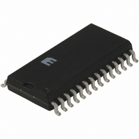
IC LED DRIVER RGB 28-SOIC

MIC5400BWM

Manufacturer Part Number
MIC5400BWM
Description
IC LED DRIVER RGB 28-SOIC
Manufacturer
Micrel Inc
Type
RGB LED Driverr
Datasheet

Specifications of MIC5400BWM

Topology
PWM
Number Of Outputs
16
Internal Driver
Yes
Type - Primary
General Purpose
Type - Secondary
RGB
Voltage - Supply
4.75 V ~ 5.5 V
Mounting Type
Surface Mount
Package / Case
28-SOIC (7.5mm Width)
Operating Temperature
-40°C ~ 125°C
Current - Output / Channel
30mA
Internal Switch(s)
Yes
Lead Free Status / RoHS Status
Contains lead / RoHS non-compliant
Voltage - Output
-
Frequency
-
Efficiency
-
General Description
The MIC5400 consists of 2 banks of 8 LED driver outputs,
each output capable of sinking up to 30mA. Each bank is
intended to drive 8 LED pixels of the same color. Most
applications will use the MIC5400 to drive pixel clusters of 4
LEDs (RRGB.) Typically two red LEDs are used for every one
green and blue to compensate for red LED brightness.
A single external resistor sets maximum drive current. Use of
an external resistor allows different color LED banks to be
biased to the same intensity. Brightness control is digitally
programmed through the serial interface. Coarse Brightness
Control is determined by two 4-bit DACs, one for each driver
bank, limiting the full-scale output to a fraction of the maxi-
mum value. Additionally, each output has Fine Brightness
Control using 10-bit resolution PWM.
Groups of drivers can be cascaded in Daisy Chain fashion.
Open circuit output faults are detected and can be read back
from the internal Status register.
Typical Application
January 2005
MIC5400
Micrel, Inc. • 1849 Fortune Drive • San Jose, CA 95131 • USA • tel + 1 (408) 944-0800 • fax + 1 (408) 944-0970 • http://www.micrel.com
V
DD
SHIFTOUT
SHFTCLK
0.01µF
SHIFTIN
LOAD
R
SET
VDD
Control and
SRegister
R
Logic
SC
MIC5400
Output B
Output A
VDDA
VDDB
BD_A
BD_B
1
Features
• 2 banks of 8 outputs
• Output characteristics:
• Current sink: 30mA
• Full protection:
• Output transitions are staggered to minimize supply
Applications
• Outdoor video screen
• Large LED display
Ordering Information
Dual, 8-Output, 14-Bit LED Video Display Driver
Part Number
MIC5400BWM
MIC5400YWM
– Programmable brightness control
– Resistor sets maximum LED current to compensate
– Current limit on each output
– Over-temperature shutdown
– Watchdog disables output under fault condition
– Power-on reset (all LEDs Off)
– Soft-start on power up and watchdog recovery
– Output open fault detection with status register
readback
transients
R
• Coarse: 4-bit resolution DAC
• Fine: 10-bit resolution PWM
variation in LEDs
SC
Junction Temp. Range
–40°C to +85°C
–40°C to +85°C
MIC5400
2.2µF
2.2µF
330½
330½
BCP69
BCP69
28-Pin Wide SOIC
28-Pin Wide SOIC
Package
MIC5400
Micrel

Related parts for MIC5400BWM

MIC5400BWM Summary of contents

Page 1

... Soft-start on power up and watchdog recovery – Output open fault detection with status register readback • Output transitions are staggered to minimize supply transients Applications • Outdoor video screen • Large LED display Ordering Information Part Number MIC5400BWM MIC5400YWM R SC MIC5400 VDDA Output A BD_A Logic Control and ...

Page 2

MIC5400 Pin Configuration Pin Description Pin Number Pin Name Pin Name 1,2,3,4 A4,A3,A2,A1 5 LOAD 6 SHFTCLK 7 VDD 8,22 GND 9 SHIFTIN 10 SHIFTOUT 11,12,13,14 B1,B2,B3,B4 15,16,17,18 B5,B6,B7,B8 19 VDDB 20 BD_B 21 REF 23 BD_A 24 VDDA 25,26,27,28 ...

Page 3

MIC5400 Absolute Maximum Ratings Supply Voltage .............................................................. +7V Input Voltage ....................................... –0. Base Drive Voltage ....................................................... +7V Output Sink Current (per output) ................................ 35mA Lead Temperature (soldering, 5 sec) ........................ 260°C Junction Temperature (T )(max) ............................... 125°C J ...

Page 4

MIC5400 Test Circuit Controller Timing Diagrams Control Register Contents Shift Register Contents Status Register Contents Linearity MIC5400 75Ω Device Under Test OUT N V Figure 1. AC Output Test Circuit SHFTCLK LOAD D D N-1 N ...

Page 5

MIC5400 Functional Diagram Data and Control Register (36 bits) 36 Bit Shift Register SHIFTIN SHFTCLK January 2005 PWM Select (3 Bits) Select Bank A/B PWM Select PWM Data A (10 Bits) PWM Data B (10 Bits) ...

Page 6

MIC5400 Address Data A 3 Bits 10 bits Q13 [Q1 = LSB] Bit ...

Page 7

MIC5400 Status A Status Open Circuit Open Circuit] 8 Bits 8 Bits D1-D8 D9-D16 Bit ...

Page 8

MIC5400 Applications Information Output Current Drive The MIC5400 includes several ways to program LED output current. These output current controls are superimposed and have an additive effect on LED output current as follows: Global Full Scale Current Limit: This function ...

Page 9

MIC5400 TIME (2.5ns/div) Output Current Sink Rise Time January 2005 Clock to Shiftout Delay Time TIME (2.5ns/div) Output Current Sink Fall Time 9 Micrel TIME (2.5ns/div) MIC5400 ...

Page 10

MIC5400 Package Information MICREL, INC. 1849 FORTUNE DRIVE SAN JOSE, CA 95131 USA + 1 (408) 944-0800 TEL The information furnished by Micrel in this datasheet is believed to be accurate and reliable. However, no responsibility is assumed by Micrel ...

Related keywords