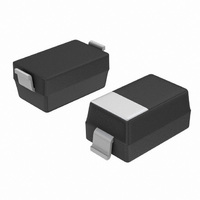
NSI45030AT1G ON Semiconductor, NSI45030AT1G Datasheet - Page 4

NSI45030AT1G
Manufacturer Part Number
NSI45030AT1G
Description
IC LED DRIVER LINEAR SOD-123
Manufacturer
ON Semiconductor
Type
Linear (Non-Switching)r
Datasheet
1.NSI45030AT1G.pdf
(6 pages)
Specifications of NSI45030AT1G
Constant Current
Yes
Topology
High Side, Linear, Low Side
Number Of Outputs
1
Type - Primary
Automotive, Backlight
Voltage - Supply
45V
Mounting Type
Surface Mount
Package / Case
SOD-123
Operating Temperature
-55°C ~ 150°C
Current - Output / Channel
30mA
Internal Switch(s)
No
Operating Supply Voltage
45 V
Maximum Supply Current
33 mA
Maximum Power Dissipation
460 mW
Maximum Operating Temperature
+ 150 C
Mounting Style
SMD/SMT
Minimum Operating Temperature
- 55 C
Lead Free Status / RoHS Status
Lead free / RoHS Compliant
Voltage - Output
-
Frequency
-
Efficiency
-
Lead Free Status / Rohs Status
Lead free / RoHS Compliant
Other names
NSI45030AT1GOSTR
Available stocks
Company
Part Number
Manufacturer
Quantity
Price
Company:
Part Number:
NSI45030AT1G
Manufacturer:
ON
Quantity:
25 000
Company:
Part Number:
NSI45030AT1G
Manufacturer:
ON
Quantity:
51 000
Part Number:
NSI45030AT1G
Manufacturer:
ON/安森美
Quantity:
20 000
APPLICATIONS
+
−
Number of LED’s that can be connected is determined by:
D1 is a reverse battery protection diode
LED’s = ((V
Example: V
LED V
(12 Vdc − 4.2 Vdc)/2.2 Vdc = 3 LEDs in series.
V
in
D1
Cathode
F
Anode
Figure 7. Typical Application Circuit
= 2.2 Vdc @ 30 mA
in
in
− Q
(30 mA each LED String)
= 12 Vdc, Q
X
V
HF3−R5570
HF3−R5570
HF3−R5570
Q1
LED
LED
LED
F
+ D1 V
X
V
F
F
)/LED V
= 3.5 Vdc, D1VF = 0.7 V
HF3−R5570
HF3−R5570
HF3−R5570
Q2
LED
LED
LED
F
)
HF3−R5570
HF3−R5570
HF3−R5570
Qx
LED
LED
LED
http://onsemi.com
4
Number of LED’s that can be connected is determined by:
D1 is a reverse battery protection diode
Example: V
LED V
(12 Vdc − (3.5 + 0.7 Vdc))/2.6 Vdc = 3 LEDs in series.
Number of Drivers = LED current/30 mA
90 mA/30 mA = 3 Drivers (Q1, Q2, Q3)
+
−
V
F
Figure 8. Typical Application Circuit
in
= 2.6 Vdc @ 90 mA
D1
Cathode
in
Anode
(90 mA each LED String)
= 12 Vdc, Q
HF3−R5570
HF3−R5570
HF3−R5570
LED
LED
LED
X
Q1
V
F
= 3.5 Vdc, D1VF = 0.7 V
Q2
Qx


