BD6067GU-E2 Rohm Semiconductor, BD6067GU-E2 Datasheet - Page 22
BD6067GU-E2
Manufacturer Part Number
BD6067GU-E2
Description
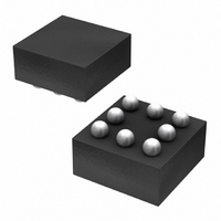
IC LED DRIVR WHITE BCKLGT 8-VCSP
Manufacturer
Rohm Semiconductor
Type
Backlight, White LEDr
Specifications of BD6067GU-E2
Topology
PWM, Step-Up (Boost)
Number Of Outputs
1
Internal Driver
Yes
Type - Primary
Backlight
Type - Secondary
White LED
Frequency
800kHz ~ 1.2MHz
Voltage - Supply
2.7 V ~ 5.5 V
Voltage - Output
30V
Mounting Type
Surface Mount
Package / Case
8-VCSP
Operating Temperature
-30°C ~ 85°C
Current - Output / Channel
30mA
Internal Switch(s)
Yes
Led Driver Application
Mobile Phones
No. Of Outputs
1
Output Current
30mA
Output Voltage
36V
Input Voltage
2.7V To 5.5V
Operating Temperature Range
-30°C To +85°C
Driver
RoHS Compliant
Lead Free Status / RoHS Status
Lead free / RoHS Compliant
Efficiency
-
Lead Free Status / Rohs Status
Details
Other names
BD6067GU-E2TR
Available stocks
Company
Part Number
Manufacturer
Quantity
Price
Company:

Part Number:
BD6067GU-E2
Manufacturer:
RICOH
Quantity:
3 000
Part Number:
BD6067GU-E2
Manufacturer:
ROHM/罗姆
Quantity:
20 000


© 2011 ROHM Co., Ltd. All rights reserved.
BD6067GU, BD6069GUT, BD6071HFN, BD6072HFN
►BD6069GUT, BD6072HFN
●Start control and brightness control
www.rohm.com
2-1) The continuous time the brightness adjustment is made by giving DC control voltage to VFB pin of BD6069GUT /
BD6069GUT/BD6072HFN can control the start conditions by its EN terminal, and power off at 0.4V or below, and power on
at 1.4V or higher. And by changing the duty of power on and off by PWM control, the LED brightness can be adjusted.
Two techniques are available for the brightness adjustment. One is discrete time (PWM) adjustment, and the other is
continuous time adjustment.
1) PWM brightness adjustment is made by giving PWM signal to EN as shown in Fig.67.
The BD6069GUT/BD6072HFN power on/off is according to the PWM signal. By this method, LED current is controlled
from 0 to the maximum current. The average LED current increases in proportion with the duty cycle of PWM signal. While
in PWM off-cycle mode, the IC and LED both consume no currents, thus providing a high-efficiency operation. And please
don’t use duty less than 5% or more than 95% of current setting for the brightness adjustment because of the influence of
turning on and off operating is large. The recommended PWM frequency is 100Hz ~ 300Hz.
BD6072HFN via a series resistor as shown in Fig.68. LED luminance (current) changed by giving DC voltage to VFB
directly. DC voltage is given from filtered one of DAC signal, or PWM signal shown in Fig.70. The advantage of this
approach is that the PWM signal to be used to control the LED brightness can be set to a high frequency (1kHz or higher).
And please don’t use duty less than 5% or more than 95% of current setting for the brightness adjustment.
VIN
Fig.68 The brightness adjustment example by DAC
VIN
Fig.70 The brightness adjustment example
LED current (ILED) is approximated by the following equation.
ILED = [{(VFB-DAC) / R1} × R2 + VFB ] / RFB
of VFB terminal by PWM (f
Fig.67 The brightness adjustment example of EN terminal by PWM (fPWM = 100Hz ~ 300Hz)
VIN
TEST
EN
VIN
TEST
EN
GNDA
GNDA
0 ~ 2.85V
GND
GND
22µH
22µH
10kHz
PWM
VIN
VOUT
VOUT
VFB
VFB
PWM
SW
SW
PWM
100kΩ
22kΩ
=10kHz)
DAC
47kΩ
33kΩ
47nF
4.7kΩ
R1
1µF
1µF
R2
VIN
TEST
EN
GNDA
RFB
30Ω
24Ω
ILED
ILED
22/29
GND
22µH
VOUT
VFB
SW
30
25
20
15
10
(VFB=500mV)
-5
5
0
1µF
2 5
2 0
1 5
1 0
30
25
20
15
10
-5
5
0
5
0
0
0
0
Fig.71 VFB PWM Control
10
24Ω
0.5
Fig.69 DAC adjustment
0.5
20 30
1
1
1.5
1.5
40
HI Du ty [%]
DAC [V]
50
2
2
60 70
2.5
2.5
3
3
80
2011.01 - Rev.C
Technical Note
3.5
3.5
90 100
4
4
Related parts for BD6067GU-E2
Image
Part Number
Description
Manufacturer
Datasheet
Request
R

Part Number:
Description:
Multifunction LED Display Panel
Manufacturer:
CARLO GAVAZZI
Datasheet:

Part Number:
Description:
Manufacturer:
Rohm Semiconductor
Datasheet:
Part Number:
Description:
Manufacturer:
Rohm Semiconductor
Datasheet:
Part Number:
Description:
Manufacturer:
Rohm Semiconductor
Datasheet:
Part Number:
Description:
Manufacturer:
Rohm Semiconductor
Datasheet:
Part Number:
Description:
Manufacturer:
Rohm Semiconductor
Datasheet:
Part Number:
Description:
Manufacturer:
Rohm Semiconductor
Datasheet:
Part Number:
Description:
Manufacturer:
Rohm Semiconductor
Datasheet:
Part Number:
Description:
Manufacturer:
Rohm Semiconductor
Datasheet:
Part Number:
Description:
Manufacturer:
Rohm Semiconductor
Datasheet:
Part Number:
Description:
Manufacturer:
Rohm Semiconductor
Datasheet:
Part Number:
Description:
Manufacturer:
Rohm Semiconductor
Datasheet:
Part Number:
Description:
Manufacturer:
Rohm Semiconductor
Datasheet: