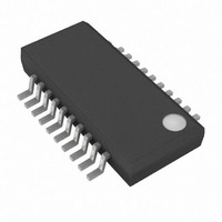
MAX3766EEP Maxim Integrated Products, MAX3766EEP Datasheet - Page 10

MAX3766EEP
Manufacturer Part Number
MAX3766EEP
Description
IC LASR DRVR 622MBPS 5.5V 20QSOP
Manufacturer
Maxim Integrated Products
Type
Laser Diode Driver (Fiber Optic)r
Datasheet
1.MAX3766EEP.pdf
(20 pages)
Specifications of MAX3766EEP
Data Rate
622Mbps
Number Of Channels
1
Voltage - Supply
4.5 V ~ 5.5 V
Current - Supply
25mA
Current - Modulation
60mA
Current - Bias
80mA
Operating Temperature
-40°C ~ 85°C
Package / Case
20-QSOP
Mounting Type
Surface Mount
Operating Supply Voltage
5 V
Supply Current
25 mA
Maximum Operating Temperature
+ 85 C
Maximum Power Dissipation
590 mW
Minimum Operating Temperature
- 40 C
Mounting Style
SMD/SMT
Lead Free Status / RoHS Status
Contains lead / RoHS non-compliant
Available stocks
Company
Part Number
Manufacturer
Quantity
Price
Company:
Part Number:
MAX3766EEP
Manufacturer:
MAXIM
Quantity:
20
Part Number:
MAX3766EEP
Manufacturer:
MAXIM/美信
Quantity:
20 000
Company:
Part Number:
MAX3766EEP+
Manufacturer:
Maxim
Quantity:
670
Company:
Part Number:
MAX3766EEP+
Manufacturer:
HITTITE
Quantity:
5 000
Part Number:
MAX3766EEP+
Manufacturer:
MAXIM/美信
Quantity:
20 000
Company:
Part Number:
MAX3766EEP+T
Manufacturer:
3M
Quantity:
230
This configuration is shown in the Typical Application
Circuits (configured for best performance), and can
be selected by connecting a capacitor (C
ground at SAFETY. In this configuration, the transmitter
is shut down when a failure is detected. It can be
restarted only by a power-on cycle or a toggle of the
ENABLE input.
During start-up, FAIL is asserted until laser power reach-
es the programmed level. The safety circuit must be dis-
abled at power-on or at transmitter enable, providing
enough time for the APC circuit to reach the programmed
laser power level.
In space-constrained designs, C
ed to provide a shutdown delay. When power is initially
applied, or when the ENABLE signal is toggled from a
logic 0 to a logic 1, the voltage at SAFETY is low, and
rises with a time constant set by C
nal 200kΩ pull-up resistor. The SAFETY signal is invert-
ed and resets the input of a reset-dominant RS flip-flop.
The internal signal FAILURE from the failure-detection
circuit is connected to the set input of the flip-flop. After
SAFETY has gone high (allowing time for the APC feed-
back loop to settle) and if internal signal FAILURE is low,
the flip-flop output is low, and the bias and modulation
outputs are allowed to remain on. Refer to Figure 5 for
a timing diagram of start-up in the latched shutdown
configuration.
622Mbps LAN/WAN Laser Driver with
Automatic Power Control and Safety Shutdown
Figure 4. Simplified Safety Circuit Schematic
10
C
SAFETY
______________________________________________________________________________________
SAFETY
ENABLE
Latched Shutdown Configuration
200k
100k
(INTERNAL)
FAILURE
V
CC
OPEN
COLLECTOR
SAFETY
SAFETY
can be select-
and an inter-
SAFETY
) to
OPEN
COLLECTOR
S
R
The duration of t
a successful start-up. After start-up, the transmitter
operates normally until a failure is detected, causing
the output currents to be shut down. The laser-current
outputs remain off until the failure condition is eliminat-
ed and the ENABLE input is toggled, or until the power
is cycled. A potential problem with this transmitter-
enable method is that a slow-rising power supply may
not enable the transmitter.
Figure 5. Start-Up Sequence Timing
V
LASER BIAS AND
MODULATION CURRENT
FAIL
OUTPUT
SAFETY
Q
CC
RESET DOMINATE
RS FLIP-FLOP
t
ON
V
SAFETY
CC
t
APC
t
SAFETY
ON (OR ENABLE SWITCHED TO ON STATE)
OUTPUT CURRENTS ENABLED AFTER A FIXED DELAY
FAIL
FAIL DEASSERTS WHEN THE APC LOOP SETTLES
must be about 10 times t
(INTERNAL)
SHDN
SAFETY FEATURES START CHECKING
THE FAILURE SIGNAL AFTER A TIME SET
BY A CAPACITOR ON THE SAFETY INPUT.
AFTER THIS TIME, THE LASER DRIVER IS
DISABLED IF A FAILURE OCCURS.
IN
SIMPLIFIED
OPEN-COLLECTOR
OUTPUT CIRCUIT
OUT
APC
for


