MAX5931AEEP+ Maxim Integrated Products, MAX5931AEEP+ Datasheet - Page 8

MAX5931AEEP+
Manufacturer Part Number
MAX5931AEEP+
Description
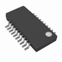
IC HOT-SWAP CTRLR TRPL 20-QSOP
Manufacturer
Maxim Integrated Products
Type
Hot-Swap Controllerr
Datasheet
1.MAX5931BEEPT.pdf
(23 pages)
Specifications of MAX5931AEEP+
Applications
General Purpose
Internal Switch(s)
No
Voltage - Supply
1 V ~ 15 V
Operating Temperature
-40°C ~ 85°C
Mounting Type
Surface Mount
Package / Case
20-SSOP (0.154", 3.91mm Width)
Lead Free Status / RoHS Status
Lead free / RoHS Compliant
Low-Voltage, Triple, Hot-Swap Controllers/
Power Sequencers/Voltage Trackers
8
MAX5930A
_______________________________________________________________________________________
10
11
12
13
14
15
16
17
18
19
20
21
22
1
2
3
4
5
6
7
8
9
PIN
MAX5931A/
MAX5931B
10
11
12
13
14
15
16
17
18
—
—
—
—
1
2
3
4
5
6
7
8
9
SENSE1
SENSE3
SENSE2
GATE1
LATCH
GATE3
GATE2
NAME
STAT1
STAT2
STAT3
LIM1
BIAS
GND
LIM3
LIM2
ON2
ON1
POL
TIM
IN1
IN3
IN2
STAT Output-Polarity Select. See Table 3 and the Status Outputs (STAT_) section.
On/Off Channel 2 Control Input. See the Mode section.
On/Off Channel 1 Control Input. See the Mode section.
Channel 1 Current-Limit Setting. Connect a resistor from LIM1 to GND to set current-trip
level. Connect to GND for the default 25mV threshold. Do not leave LIM1 unconnected.
Channel 1 Supply Input. Connect to a 1V to 15V supply voltage and to one end of R
Bypass with a 0.1µF capacitor to ground.
Channel 1 Current-Sense Input. Connect SENSE1 to the drain of an external MOSFET and
to one end of R
Channel 1 Gate-Drive Output. Connect to the gate of the external n-channel MOSFET.
Op en- D r ai n S tatus S i g nal for C hannel 1. S TAT1 asser ts w hen hot sw ap i s successful and t
has el ap sed . S TAT1 d easser ts i f ON 1 i s l ow , or i f channel 1 i s tur ned off for any faul t cond i ti on.
Op en- D r ai n S tatus S i g nal for C hannel 2. S TAT2 asser ts w hen hot sw ap i s successful and t
has el ap sed . S TAT2 d easser ts i f ON 2 i s l ow , or i f channel 2 i s tur ned off for any faul t cond i ti on.
Startup Timer Setting. Connect a resistor from TIM to GND to set the startup period. Leave
TIM unconnected for the default startup period of 9ms. R
500kΩ.
Latch/Autoretry Selection Input. Connect LATCH to GND for autoretry mode after a fault.
Leave LATCH unconnected for latch mode.
Open-Drain Status Signal for Channel 3. STAT3 asserts when hot swap is successful and
t
condition.
S up p l y Refer ence Outp ut. The hi g hest sup p l y i s avai l ab l e at BIAS for fi l ter i ng . C onnect a 1nF
to 10nF cer am i c cap aci tor fr om BIAS to GN D . N o other connecti ons ar e al l ow ed to BIAS .
Ground
Channel 3 Gate-Drive Output. Connect to gate of external n-channel MOSFET.
Channel 3 Current-Sense Input. Connect SENSE3 to the drain of an external MOSFET and
to one end of R
Channel 3 Supply Input. Connect to a supply voltage from 1V to 15V and to one end of
R
Channel 3 Current-Limit Setting. Connect a resistor from LIM3 to GND to set current-trip
level. Connect to GND for the default 25mV threshold. Do not leave LIM3 unconnected.
Channel 2 Gate-Drive Output. Connect to gate of external n-channel MOSFET.
Channel 2 Current-Sense Input. Connect SENSE2 to the drain of an external MOSFET and
to one end of R
Channel 2 Supply Input. Connect to a 1V to 15V supply voltage and to one end of R
Bypass with a 0.1µF capacitor to ground.
Channel 2 Current-Limit Setting. Connect a resistor from LIM2 to GND to set current-trip
level. Connect to GND for the default 25mV threshold. Do not leave LIM2 unconnected.
START
SENSE3
has elapsed. STAT3 deasserts if ON3 is low, or if channel 3 is turned off for any fault
. Bypass with a 0.1µF capacitor to ground.
SENSE1
SENSE3
SENSE2
.
.
.
FUNCTION
TIM
must be between 4kΩ and
Pin Description
SENSE1
SENSE2
S T AR T
S T AR T
.
.


