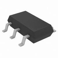
LTC4210-2CS6#TRM Linear Technology, LTC4210-2CS6#TRM Datasheet - Page 3

LTC4210-2CS6#TRM
Manufacturer Part Number
LTC4210-2CS6#TRM
Description
IC CONTROLLER HOT SWAP TSOT23-6
Manufacturer
Linear Technology
Type
Hot-Swap Controllerr
Datasheet
1.LTC4210-1CS6TRMPBF.pdf
(20 pages)
Specifications of LTC4210-2CS6#TRM
Applications
General Purpose
Internal Switch(s)
No
Voltage - Supply
2.7 V ~ 16.5 V
Operating Temperature
0°C ~ 70°C
Mounting Type
Surface Mount
Package / Case
SOT-23-6 Thin, TSOT-23-6
Linear Misc Type
Positive Low Voltage
Family Name
LTC4210-2
Package Type
TSOT-23
Operating Supply Voltage (min)
2.7V
Operating Supply Voltage (max)
16.5V
Operating Temperature (min)
0C
Operating Temperature (max)
70C
Operating Temperature Classification
Commercial
Product Height (mm)
0.9mm
Product Length (mm)
2.9mm
Mounting
Surface Mount
Pin Count
6
Lead Free Status / RoHS Status
Contains lead / RoHS non-compliant
Other names
LTC4210-2CS6#TRMTR
Available stocks
Company
Part Number
Manufacturer
Quantity
Price
ELECTRICAL CHARACTERISTICS
temperature range, otherwise specifications are T
SYMBOL
t
t
t
Note 1: Absolute Maximum Ratings are those values beyond which the life
of a device may be impaired.
Note 2: All currents into device pins are positive; all currents out of device
pins are negative. All voltages are referenced to ground unless otherwise
specified.
TYPICAL PERFOR A CE CHARACTERISTICS
OFF(TMRHIGH)
OFF(ONLOW)
OFF(VCCLOW)
4.0
3.5
3.0
2.5
2.0
1.5
1.0
0.5
40
35
30
25
20
15
10
0
5
0
0
0
Supply Current vs Supply Voltage
V
T
T
A
GATE
A
= 25 C
2
2
= 25 C
4
4
vs Supply Voltage
PARAMETER
Turn-Off Time (TIMER Rise to GATE Fall)
Turn-Off Time (ON Fall to GATE Fall)
Turn-Off Time (V
SUPPLY VOLTAGE (V)
SUPPLY VOLTAGE (V)
6
6
8
8
10
10
12
12
CC
14
14
Fall to IC Reset)
W
16
16
18
4210 G01
18
4210 G04
U
20
20
4.0
3.5
3.0
2.5
2.0
1.5
1.0
0.5
A
40
35
30
25
20
15
10
0
5
0
–75
–75
= 25 C. V
Supply Current vs Temperature
V
CONDITIONS
V
V
V
GATE
TIMER
ON
CC
–50
–50
= 5V to 2V Step, V
= 5V to 0V Step, V
The
–25
–25
vs Temperature
= 0V to 2V Step, V
CC
TEMPERATURE ( C)
TEMPERATURE ( C)
0
0
= 5V, unless otherwise noted. (Note 2)
denotes specifications which apply over the full operating
25
25
Note 3: An internal Zener on the GATE pin clamps the charge pump
voltage to a typical maximum voltage of 26V. External overdrive of the
GATE pin beyond the internal Zener voltage may damage the device.
Without a limiting resistor, the GATE capacitance must be <0.15 F at
maximum V
Zener diode may be used.
50
50
ON
CC
75 100 125
75 100 125
= 5V
= 5V
CC
V
V
V
V
= V
V
V
V
V
CC
CC
CC
CC
CC
CC
CC
CC
CC
= 15V
= 12V
= 15V
= 12V
ON
= 5V
= 3V
= 5V
= 3V
. If a lower GATE pin clamp voltage is desired, an external
4210 G02
4210 G05
= 5V
150
150
LTC4210-1/LTC4210-2
–10.0
–10.5
–11.0
–11.5
–12.0
–8.0
–8.5
–9.0
–9.5
2.65
2.60
2.55
2.50
2.45
2.40
2.35
2.30
2.25
–75
0
Undervoltage Lockout Threshold
vs Temperature
I
GATEUP
T
MIN
A
–50
2
= 25 C
–25
4
vs Supply Voltage
SUPPLY VOLTAGE (V)
6
TEMPERATURE ( C)
TYP
V
V
0
30
30
1
CC
CC
8
RISING
FALLING
25
10
50
MAX
12
75 100 125
14
16
18
UNITS
4210 G06
421012f
4210 G03
3
150
20
s
s
s


