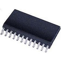
CS5466-ISZR Cirrus Logic Inc, CS5466-ISZR Datasheet - Page 2

CS5466-ISZR
Manufacturer Part Number
CS5466-ISZR
Description
IC ENERGY METERING 1PHASE 24SSOP
Manufacturer
Cirrus Logic Inc
Datasheet
1.CS5466-ISZ.pdf
(16 pages)
Specifications of CS5466-ISZR
Input Impedance
30 KOhm
Measurement Error
0.1%
Voltage - I/o High
0.8V
Voltage - I/o Low
0.2V
Current - Supply
2.9mA
Voltage - Supply
4.75 V ~ 5.25 V
Operating Temperature
-40°C ~ 85°C
Mounting Type
Surface Mount
Package / Case
24-SSOP
Meter Type
Single Phase
For Use With
598-1011 - BOARD EVAL & SOFTWARE CS5466 ADC
Lead Free Status / RoHS Status
Lead free / RoHS Compliant
TABLE OF CONTENTS
LIST OF FIGURES
LIST OF TABLES
2
1. OVERVIEW ............................................................................................................................... 3
2. PIN DESCRIPTION ................................................................................................................... 4
3. CHARACTERISTICS & SPECIFICATIONS ............................................................................. 5
4. THEORY OF OPERATION ..................................................................................................... 10
5. FUNCTIONAL DESCRIPTION ............................................................................................... 11
6. PACKAGE DIMENSIONS ....................................................................................................... 15
7. REVISION HISTORY................................................................................................................ 16
Figure 1. Timing Diagram for E1, E2 and FOUT (Not to Scale) ...................................................... 8
Figure 2. Data Flow ....................................................................................................................... 10
Figure 3. Oscillator Connection ..................................................................................................... 13
Figure 4. Typical Connection Diagram .......................................................................................... 14
Table 1. Current Channel PGA Setting ......................................................................................... 11
Table 2. Maximum Frequency for E1, E2, and FOUT ................................................................... 12
Table 3. Absolute Max Frequency on E1 and E2.......................................................................... 12
RECOMMENDED OPERATING CONDITIONS ....................................................................... 5
ANALOG CHARACTERISTICS ................................................................................................ 5
VOLTAGE REFERENCE ......................................................................................................... 6
DIGITAL CHARACTERISTICS ................................................................................................. 7
SWITCHING CHARACTERISTICS .......................................................................................... 8
ABSOLUTE MAXIMUM RATINGS ........................................................................................... 9
4.1 Digital Filters .................................................................................................................... 10
4.2 Active Power Computation ............................................................................................... 10
5.1 Analog Inputs ................................................................................................................... 11
5.2 High-pass Filter ................................................................................................................ 11
5.3 Energy Pulse Outputs ...................................................................................................... 11
5.4 Energy Direction Indicator ............................................................................................... 13
5.5 Power-on Reset ............................................................................................................... 13
5.6 Oscillator Characteristics ................................................................................................. 13
5.7 Basic Application Circuit .................................................................................................. 14
5.1.1 Voltage Channel .................................................................................................. 11
5.1.2 Current Channel .................................................................................................. 11
5.3.1 Pulse Output Format. .......................................................................................... 11
5.3.2 Selecting Frequency of E1 and E2 ...................................................................... 11
5.3.3 Selecting Frequency of FOUT ............................................................................. 12
5.3.4 Absolute Max Frequency on E1 and E2 .............................................................. 12
5.3.5 E1 and E2 Frequency Calculation ....................................................................... 13
CS5466
DS659F1


