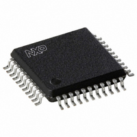
OM4068H/2,518 NXP Semiconductors, OM4068H/2,518 Datasheet - Page 8

OM4068H/2,518
Manufacturer Part Number
OM4068H/2,518
Description
IC LCD DRIVER 44-QFP
Manufacturer
NXP Semiconductors
Datasheet
1.OM4068H2518.pdf
(28 pages)
Specifications of OM4068H/2,518
Package / Case
44-MQFP, 44-PQFP
Display Type
LCD
Configuration
32 Segment
Interface
Serial
Current - Supply
12µA
Voltage - Supply
2.5 V ~ 5.5 V
Operating Temperature
-40°C ~ 105°C
Mounting Type
Surface Mount
Number Of Digits
12
Number Of Segments
96
Maximum Clock Frequency
2.1 MHz
Operating Supply Voltage
2.5 V to 5.5 V
Maximum Power Dissipation
500 mW
Maximum Operating Temperature
+ 105 C
Attached Touch Screen
No
Maximum Supply Current
25 uA
Minimum Operating Temperature
- 40 C
Lead Free Status / RoHS Status
Lead free / RoHS Compliant
Digits Or Characters
-
Lead Free Status / Rohs Status
Lead free / RoHS Compliant
Other names
568-4513-2
935276329518
OM4068HB-T
OM4068HB-T
935276329518
OM4068HB-T
OM4068HB-T
Available stocks
Company
Part Number
Manufacturer
Quantity
Price
Company:
Part Number:
OM4068H/2,518
Manufacturer:
NXP Semiconductors
Quantity:
10 000
Philips Semiconductors
FUNCTIONAL DESCRIPTION
The OM4068 is a low-power LCD driver designed to
interface with any microprocessor/microcontroller and a
wide variety of LCDs. It can drive any static or multiplexed
LCD containing up to three backplanes and
up to 96 segments.
Table 1 Selection of display configurations
The host microprocessor/microcontroller maintains the
3-line bus communication channel with OM4068.
The internal oscillator requires no external components.
The appropriate intermediate biasing voltage for the
multiplexed LCD waveforms are generated on-chip.
1998 Jun 18
handbook, full pagewidth
LCD driver for low multiplex rates
(1) 28 segment drivers for DIP40 package.
BACKPLANES
3
2
1
V DD
V SS
NUMBER OF
MICROCONTROLLER
MICROPROCESSOR/
HOST
SEGMENTS
DISPLAY
96
64
32
Fig.4 Typical system configuration.
SCLK
SDIN
SCE
DIGITS
M1 M0
V DD
12
7-SEGMENTS NUMERIC
8
4
8
OM4068
The display configurations possible with the OM4068
depend on the number of active backplane outputs
required; a selection of display configurations is given in
Table 1.
A typical system (MUX 1 : 3) is shown in Fig.4.
The only other connections required to complete the
system are to the power supplies (V
suitable capacitors to decouple the V
V
SS
.
V LCD
V SS
32 segment drivers
3 backplanes
INDICATOR
SYMBOLS
12
8
4
SDOUT
(1)
LCD PANEL
(up to 96
elements)
96 dots (3
64 dots (2
32 dots (1
SS
MBK818
Product specification
LCD
, V
DOT MATRIX
DD
and V
OM4068
and V
DD
32)
32)
32)
LCD
pins to
) and


