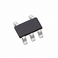
ZXCT1010E5TA Diodes Zetex, ZXCT1010E5TA Datasheet - Page 6

ZXCT1010E5TA
Manufacturer Part Number
ZXCT1010E5TA
Description
IC CURRENT MONITOR 1% SOT-23-5
Manufacturer
Diodes Zetex
Datasheet
1.ZXCT1010E5TA.pdf
(9 pages)
Specifications of ZXCT1010E5TA
Function
Current Monitor
Sensing Method
High-Side
Accuracy
±1%
Voltage - Input
2.5 ~ 20 V
Current - Output
10mA
Operating Temperature
-40°C ~ 85°C
Mounting Type
Surface Mount
Package / Case
SOT-23-5, SC-74A, SOT-25
Operating Temperature (max)
85C
Operating Temperature (min)
-40C
Pin Count
5
Mounting
Surface Mount
Package Type
SOT-23
Case Length
3.1(Max)mm
Screening Level
Industrial
Lead Free Status / RoHS Status
Lead free / RoHS Compliant
Other names
ZXCT1010TA
ZXCT1010TR
ZXCT1010TR
Available stocks
Company
Part Number
Manufacturer
Quantity
Price
Part Number:
ZXCT1010E5TA
Manufacturer:
ZETEX
Quantity:
20 000
APPLICATIONS INFORMATION (Continued)
Charger Input
Li-Ion Charger Circuit
The above figure shows the ZXCT1010 supporting
the Benchmarq bq2954 Charge Management IC.
Most of the support components for the bq2954 are
omitted for clarity. This design also uses the Zetex
FZT789A high current Super- PNP as the switching
transistor in the DC-DC step down converter and the
FMMT451 as the drive NPN for the FZT789A. The
circuit can be configured to charge up to four Li-Ion
cells at a charge current of 1.25A. Charge can be
terminated on maximum voltage, selectable
minimum current, or maximum time out. Switching
frequency of the PWM loop is approximately 120kHz.
ZXCT1010
support components omitted for clarity
bq2954
S E M I C O N D U C T O R S
5V
BC81725
MOD pin
SNS pin
BAS16
FMMT451
FZT789A
1kΩ
220Ω
10µH
ZHCS1000
140µH
100Ω
100Ω
V in
I out
0.2Ω
ZXCT1010
+
-
Load
To Battery +
6
Bi-Directional Current Sensing
The ZXCT1010 can be used to measure current
bi-directionally, if two devices are connected as
shown below.
If the voltage V1 is positive with respect to the
voltage V2 the lower device will be active, delivering
a proportional output current to Rout. Due to the
polarity of the voltage across Rsense, the upper
device will be inactive and will not contribute to the
current delivered to Rout. When V2 is more positive
than V1, current will be flowing in the opposite
direction, causing the upper device to be active
instead.
Non-linearity will be apparent at small values of
Vsense due to offset current contribution. Devices
can use separate output resistors if the current
direction is to be monitored independently.
Bi-directional Transfer Function
Output Current v Sense Voltage
5
4
3
2
1
0
-400
Sense Voltage (mV)
-200
0
200
ISSUE 10 - JULY 2007
400


