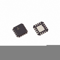
ISL6292-1CR4Z-T Intersil, ISL6292-1CR4Z-T Datasheet - Page 7

ISL6292-1CR4Z-T
Manufacturer Part Number
ISL6292-1CR4Z-T
Description
IC BATT CHRGR LI-ION 4.1V 16-QFN
Manufacturer
Intersil
Datasheet
1.ISL6292-2CR5Z-T.pdf
(20 pages)
Specifications of ISL6292-1CR4Z-T
Function
Charge Management
Battery Type
Lithium-Ion (Li-Ion), Lithium-Polymer (Li-Pol)
Voltage - Supply
4.3 V ~ 6.5 V
Operating Temperature
-20°C ~ 70°C
Mounting Type
Surface Mount
Package / Case
16-VQFN Exposed Pad, 16-HVQFN, 16-SQFN, 16-DHVQFN
Lead Free Status / RoHS Status
Lead free / RoHS Compliant
Typical Operating Performance
Pin Descriptions
VIN (Pin 1, 15, 16 for 4x4, 5x5; Pin 1 for 3x3)
VIN is the input power source. Connect to a wall adapter.
FAULT (Pin 2)
FAULT is an open-drain output indicating fault status. This
pin is pulled to LOW under any fault conditions.
STATUS (Pin 3)
STATUS is an open-drain output indicating charging and
inhibit states. The STATUS pin is pulled LOW when the
charger is charging a battery.
Time (Pin 4)
The TIME pin determines the oscillation period by
connecting a timing capacitor between this pin and GND.
The oscillator also provides a time reference for the charger.
GND (Pin 5)
GND is the connection to system ground.
TOEN (Pin 6 for 4x4, 5x5; N/A for 3x3)
TOEN is the TIMEOUT enable input pin. Pulling this pin to
LOW disables the TIMEOUT charge-time limit for the fast
charge modes. Leaving this pin HIGH or floating enables the
TIMEOUT limit.
FIGURE 15. STATUS/FAULT PIN VOLTAGE vs CURRENT WHEN THE OPEN-DRAIN MOSFET TURNS ON
7
28
24
20
16
12
8
4
0
0.0 0.5
The test conditions for the Typical Operating Performance are: V
R
IREF
1.0 1.5 2.0
= R
STATUS PIN VOLTAGE (V)
IMIN
ISL6292
= 80kΩ, V
2.5 3.0 3.5 4.0
EN (Pin 7 for 4x4, 5x5; Pin 6 for 3x3)
EN is the enable logic input. Connect the EN pin to LOW to
disable the charger or leave it floating to enable the charger.
V2P8 (Pin 8 for 4x4, 5x5; Pin 7 for 3x3)
This is a 2.8V reference voltage output. This pin outputs a
2.8V voltage source when the input voltage is above POR
threshold and outputs zero otherwise. The V2P8 pin can be
used as an indication for adapter presence.
IREF (Pin 9 for 4x4, 5x5; Pin 8 for 3x3)
This is the programming input for the constant charging
current.
IMIN (Pin 10 for 4x4, 5x5; N/A for 3x3)
IMIN is the programmable input for the end-of-charge
current.
TEMP (Pin 11 for 4x4, 5x5; Pin 9 for 3x3)
TEMP is the input for an external NTC thermistor. The TEMP
pin is also used for battery removal detection.
VBAT (Pin 12, 13, 14 for 4x4, 5x5; Pin 10 for 3x3)
VBAT is the connection to the battery. Typically a 10µF
Tantalum capacitor is needed for stability when there is no
battery attached. When a battery is attached, only a 0.1µF
ceramic capacitor is required.
BAT
= 3.7V, Unless Otherwise Noted. (Continued)
4.5 5.0
IN
= 5V, T
A
= +25°C,
December 17, 2007
FN9105.9


