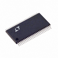
LTC1760CFW Linear Technology, LTC1760CFW Datasheet - Page 38

LTC1760CFW
Manufacturer Part Number
LTC1760CFW
Description
IC MANAGER BATTERY DUAL 48TSSOP
Manufacturer
Linear Technology
Datasheet
1.LTC1760CFWPBF.pdf
(44 pages)
Specifications of LTC1760CFW
Function
Charge Management
Battery Type
Smart Batteries
Voltage - Supply
6 V ~ 28 V
Operating Temperature
0°C ~ 70°C
Mounting Type
Surface Mount
Package / Case
48-TFSOP (0.240", 6.10mm Width)
Lead Free Status / RoHS Status
Contains lead / RoHS non-compliant
Available stocks
Company
Part Number
Manufacturer
Quantity
Price
Company:
Part Number:
LTC1760CFW
Manufacturer:
Linear Technology
Quantity:
1 855
Company:
Part Number:
LTC1760CFW
Manufacturer:
ST
Quantity:
215
Part Number:
LTC1760CFW
Manufacturer:
LT/凌特
Quantity:
20 000
Company:
Part Number:
LTC1760CFW#PBF
Manufacturer:
LT
Quantity:
2
Part Number:
LTC1760CFW#PBF
Manufacturer:
LINEAR/凌特
Quantity:
20 000
LTC1760
APPLICATIO S I FOR ATIO
The relatively high ESR of an aluminum electrolytic for
C15, located at the AC adapter input terminal, is helpful in
reducing ringing during the hot-plug event. Refer to AN88
for more information.
Highest possible voltage rating on the capacitor will mini-
mize problems. Consult with the manufacturer before use.
Alternatives include new high capacity ceramic (at least
20µF) from Tokin, United Chemi-Con/Marcon, et al. Other
alternative capacitors include OSCON capacitors from
Sanyo.
The output capacitor (C
output switching current ripple. The general formula for
capacitor current is:
For example:
EMI considerations usually make it desirable to minimize
ripple current in the battery leads, and beads or inductors
may be added to increase battery impedance at the 300kHz
switching frequency. Switching ripple current splits be-
tween the battery and the output capacitor depending on
the ESR of the output capacitor and the battery imped-
ance. If the ESR of C
is raised to 4Ω with a bead or inductor, only 5% of the
current ripple will flow in the battery.
Power Path and Charge MUX MOSFET Selection
Three pairs of P-channel MOSFETs must be used with the
wall adapter and the two battery discharge paths. Two
pairs of N-channel MOSFETs must be used with the
battery charge path. The nominal gate drive levels are set
by the clamp drive voltage of their respective control
circuitry. This voltage is typically 6.25V. Consequently,
logic-level threshold MOSFETs must be used. Pay close
attention to the B
well; many of the logic level MOSFETs are limited to 30V
or less.
38
V
f = 300kHz, I
I
RMS
DCIN
=
= 19V, V
0.29 (V
RMS
(L1)(f)
BAT
VDSS
OUT
U
BAT
= 0.41A.
= 12.6V, L1 = 10µH, and
specification for the MOSFETs as
) 1 –
is 0.2Ω and the battery impedance
(
OUT
U
) is also assumed to absorb
V
V
DCIN
BAT
W
)
U
Selection criteria for the power MOSFETs include the “ON”
resistance R
current. For the N-channel charge path, the maximum
current is the maximum programmed current to be used.
For the P-channel discharge path maximum current typi-
cally occurs at end of life of the battery when using only
one battery. The upper limit of R
of the actual power dissipation capability of a given
MOSFET package that must take into account the PCB
layout. As a starting point, without knowing what the PCB
dissipation capability would be, derate the package power
rating by a factor of two.
If you are using a dual MOSFET package with both MOSFETs
in series, you must cut the package power rating in half
again and recalculate.
If you use identical MOSFETs for both battery paths,
voltage drops will track over a wide current range. The
LTC1760 linear 25mV CV drop regulation will not occur
until the current has dropped below:
However, if you try to use the above equation to determine
R
R
available at this time. The need for the LTC1760 voltage
drop regulation only comes into play for parallel battery
configurations that terminate charge or discharge using
voltage. At first this seems to be a problem, but there are
several factors helping out:
1. When batteries are in parallel current sharing, the
2. Most batteries that charge in constant voltage mode,
DS(ON)
DS(ON)
current flow through any one battery is less than if it is
running stand-alone.
such as Li-ion, charge terminate at a current value of
R
R
I
LINEARMAX
DS ON MAX
DS ON MAX
(
(
to force linear mode at full current, the MOSFET
value becomes unreasonably low for MOSFETs
)
)
DS(ON)
=
=
=
2
P
P
2
R
, input voltage and maximum output
( )
MOSFETDUAL
MOSFET
I
4
DS ON MAX
MAX
25
( )
I
(
MAX
mV
2
)
2
DS(ON)
value is a function
1760f


