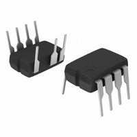
NCP1377PG ON Semiconductor, NCP1377PG Datasheet - Page 12

NCP1377PG
Manufacturer Part Number
NCP1377PG
Description
IC CTRLR PWM CM OVP UVLO 8DIP
Manufacturer
ON Semiconductor
Datasheet
1.NCP1377BPG.pdf
(17 pages)
Specifications of NCP1377PG
Output Isolation
Isolated
Frequency Range
100kHz
Voltage - Input
8.2 ~ 18 V
Operating Temperature
0°C ~ 125°C
Package / Case
8-DIP (0.300", 7.62mm), 7 Leads
Number Of Outputs
1
Output Voltage
18 V
Output Current
500 mA
Mounting Style
Through Hole
Switching Frequency
100 KHz
Maximum Operating Temperature
+ 150 C
Fall Time
20 ns
Rise Time
40 ns
Synchronous Pin
No
Topology
Flyback
Lead Free Status / RoHS Status
Lead free / RoHS Compliant
Other names
NCP1377PGOS
Available stocks
Company
Part Number
Manufacturer
Quantity
Price
Part Number:
NCP1377PG
Manufacturer:
ON/安森美
Quantity:
20 000
Soft−Start
soften the constraints occurring in the power supply during
startup. It is activated during the power on sequence. As
soon as Vcc reaches Vcc
increased from nearly zero up to the maximum clamping
level (e.g. 1.0 V). The Soft−Start is also activated during
the overcurrent burst (OCP) sequence. Every restart
attempt is followed by a Soft−Start activation. Generally
speaking, the Soft−Start will be activated when Vcc ramps
up either from zero (fresh power−on sequence) or 5.6 V, the
latchoff voltage occurring during OCP.
Calculating the Vcc Capacitor
consumption as soon as Vcc reaches Vcc
a NCP1377 is used and drives a MOSFET with a 30 nC
total gate charge (Qg). The total average current is thus
made of Icc1 (1.0 mA) plus the driver current, Fsw x Qg or
1.8 mA. The total current is therefore 2.8 mA. The DV
available to fully startup the circuit (e.g. never reach the
7.5 V UVLO during power on) is 12.5 – 7.5 = 5.0 V. We
have a capacitor which then needs to supply the NCP1377
with 2.8 mA during a given time until the auxiliary supply
takes over. Suppose that this time was measured at around
The NCP1377 features an internal 1.0 ms Soft−Start to
The Vcc capacitor can be calculated knowing the IC
ON
, the peak current is gradually
Vcc
Figure 28. Typical Waveforms in Short Circuit Conditions
ON
ON
. Suppose that
Vcc
off
Vcc
http://onsemi.com
latch
12
15 ms. CV
the latchoff phase, the current consumption drops to ICC3
or 220 mA. We can now calculate how long this latchoff
phase will last: (7.5–5.6) x 22 m/220 u = 190 ms.
Protecting Pin 8 Against Negative Spikes
negative voltages that could appear on its pins. To avoid
any adverse latchup of the IC, we strongly recommend to
insert a resistor R
prevents from adversely latching the controller in case of
negative spikes appearing on the bulk capacitor during the
power−off sequence. A typical value of 6.8 kW/0.5 W is
suitable. This resistor does not dissipate any power since it
only sees current during the startup sequence and during
overload. Calculations actually involve the minimum
voltage on pin8 necessary to fully activate the current
source. This minimum voltage being 40 V, therefore R
shall be less than: (Vbulk
Operating Shots
Vin = 120 VDC with a transformer featuring a 800 mH
primary inductance.
C w 8.6 mF
As any CMOS controller, NCP1377 is sensitive to
Following are some oscilloscope shots captured at
Driving Pulses
Vcc
CC
. Select a 22 mF/16 V and this will fit. During
is calculated using the equation
HV
in series with pin8. This resistor
min
–40)/6.0 m.
C +
Dt · i
DV
HV
or


