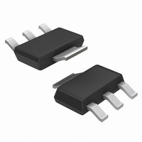
NCP1013ST100T3G ON Semiconductor, NCP1013ST100T3G Datasheet - Page 19

NCP1013ST100T3G
Manufacturer Part Number
NCP1013ST100T3G
Description
IC OFFLINE SWIT SMPS CM SOT223
Manufacturer
ON Semiconductor
Datasheet
1.NCP1010ST100T3G.pdf
(24 pages)
Specifications of NCP1013ST100T3G
Output Isolation
Isolated
Frequency Range
90 ~ 110kHz
Voltage - Input
8.5 ~ 10 V
Voltage - Output
700V
Power (watts)
19W
Operating Temperature
-40°C ~ 125°C
Package / Case
TO-261-4, TO-261AA, SOT-223-4
Duty Cycle (max)
72 %
Mounting Style
SMD/SMT
Switching Frequency
110 KHz
Operating Supply Voltage
- 0.3 V to + 10 V
Maximum Operating Temperature
+ 150 C
Synchronous Pin
No
Topology
Flyback
Lead Free Status / RoHS Status
Lead free / RoHS Compliant
Other names
NCP1013ST100T3G
NCP1013ST100T3GOSTR
NCP1013ST100T3GOSTR
Available stocks
Company
Part Number
Manufacturer
Quantity
Price
Part Number:
NCP1013ST100T3G
Manufacturer:
ON/安森美
Quantity:
20 000
Typical Application Examples
A 6.5 W NCP1012- -Based Flyback Converter
delivering 6.5 W from a universal input. The board uses the
Dynamic Self- -Supply and a simplified Zener- -type
the following results:
CEE7.5/2
Figure 28 shows a converter built with a NCP1012
The converter built according to Figure 29 layouts, gave
Efficiency at Vin = 100 Vac and Pout = 6.5 W = 75.7%
Efficiency at Vin = 230 Vac and Pout = 6.5 W = 76.5%
J1
47 R
R1
1
2
2
Figure 29. The NCP1012- -Based PCB Layout . . . and its Associated Component Placement
D1
1N4007
D3
1N4007
Figure 28. An NCP1012- -Based Flyback Converter Delivering 6.5 W
D2
1N4007
D4
1N4007
E1
10 m/400 V
E2
10 m/16 V
http://onsemi.com
19
R2
150 k
1
2
3
7
feedback. This configuration was selected for cost reasons
and a more precise circuitry can be used, e.g. based on a
TL431:
V
GND
GND
GND
CC
NCP1012
IC1
C1
2.2 nF
GND
HV
FB
U160
4 4
8
5
D5
1
4
PC817
2n2/Y
TR1
C2
IC2
8
7
6
5
470 m/25 V
B150
100 R
D6
E3
R3
11 V
ZD1
R4
180 R
2
1
CZM5/2
J2


