SY10E116JC Micrel Inc, SY10E116JC Datasheet - Page 3
SY10E116JC
Manufacturer Part Number
SY10E116JC
Description
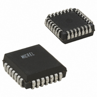
IC LINE RCVR QUINT DIFF 28-PLCC
Manufacturer
Micrel Inc
Series
10Er
Datasheet
1.SY100E116JY.pdf
(4 pages)
Specifications of SY10E116JC
Logic Type
Differential Receiver
Supply Voltage
4.2 V ~ 5.5 V
Number Of Bits
5
Operating Temperature
-40°C ~ 85°C
Mounting Type
Surface Mount
Package / Case
28-LCC (J-Lead)
Lead Free Status / RoHS Status
Contains lead / RoHS non-compliant
Available stocks
Company
Part Number
Manufacturer
Quantity
Price

Part Number:
SY10E116JC
Manufacturer:
SYNERGY
Quantity:
20 000


Micrel, Inc.
Q
V
Notes:
1. V
2. V
V
Notes:
1. Minimum input swing for which AC parameters are guaranteed.
2. Within-device skew is defined as identical transitions on similar paths through a device.
3. Duty cycle skew is defined only for differential operation when the delays are measured from the cross point of the inputs to the cross point of the
M9999-032006
hbwhelp@micrel.com or (408) 955-1690
Symbol
V
I
I
V
V
IH
EE
Symbol
t
V
t
t
t
t
EE
EE
n
PD
skew
skew
r
f
BB
PP (DC)
CMR
LOGIC EQUATION
DC ELECTRICAL CHARACTERISTICS
AC ELECTRICAL CHARACTERISTICS
and the input swing is greater than V
PP (DC)
outputs.
= D
PP
CMR
= V
= V
is the minimum differential input voltage required to assure full ECL levels are present at the outputs.
n
is referenced to the most positive side of the differential input signal. Normal operation is obtained when the "HIGH" input is within the V
EE
EE
Output Reference
Voltage
Input HIGH Current
Power Supply Current
Input Sensitivity
Common Mode Range
(Min.) to V
(Min.) to V
Propagation Delay to
Output
Input Sensitivity
Within-Device Skew
Dn to Qn, Qn
Duty Cycle Skew
t
Rise/Fall Time
20% to 80%
PLH –
Parameter
t
Parameter
PHL
EE
EE
(Max.); V
(Max.); V
(1)
D (S.E.)
(1)
(3)
100E
100E
10E
10E
(2)
D
(2)
PP
CC
CC
Min.
–1.43
–1.43
(min.) and <1V.
150
150
150
250
Min. Typ.
–2.0
150
—
—
—
—
—
= V
= V
T
T
A
A
CCO
CCO
= –40 C
= –40 C
Typ.
300
300
375
29
29
—
—
—
—
—
—
50
10
= GND
= GND
–1.30
–1.26
Max.
Max.
–0.6
200
500
550
150
625
35
35
—
—
—
–1.38
–1.38
Min.
–2.0
Min.
150
150
200
150
275
—
—
—
—
—
T
T
3
A
A
Typ.
Typ.
300
300
375
= 0 C
—
—
—
29
29
—
—
= 0 C
—
50
10
–1.27
–1.26
Max.
Max.
–0.6
200
450
500
575
35
35
—
—
—
—
–1.35
–1.38
Min.
–2.0
Min.
150
150
200
150
275
—
—
—
—
—
T
T
A
A
= +25 C
= +25 C
Typ.
Typ.
300
300
375
29
29
50
—
—
—
—
—
—
10
–1.25
–1.26
Max.
Max.
–0.6
200
450
500
575
35
35
—
—
—
—
–1.31
–1.38
Min.
Min.
–2.0
150
150
200
150
275
—
—
—
—
—
T
T
A
A
= +85 C
= +85 C
Typ.
Typ.
300
300
375
29
33
—
—
—
—
—
—
50
10
–1.19
–1.26
Max.
Max.
–0.6
200
450
500
575
SY100E116
35
40
—
—
—
—
SY10E116
CMR
Unit
Unit
range
mA
mV
mV
ps
ps
ps
ps
V
V
A
Related parts for SY10E116JC
Image
Part Number
Description
Manufacturer
Datasheet
Request
R


Part Number:
Description:
Manufacturer:
Micrel Semiconductor
Datasheet:
Part Number:
Description:
Manufacturer:
Micrel Semiconductor
Datasheet:
Part Number:
Description:
Manufacturer:
Micrel Semiconductor
Datasheet:
Part Number:
Description:
Manufacturer:
Micrel Semiconductor
Datasheet:
Part Number:
Description:
Manufacturer:
Micrel Semiconductor
Datasheet:
Part Number:
Description:
Manufacturer:
Micrel Semiconductor
Datasheet:
Part Number:
Description:
Manufacturer:
Micrel Semiconductor
Datasheet:
Part Number:
Description:
Manufacturer:
Micrel Semiconductor
Datasheet:
Part Number:
Description:
Manufacturer:
Micrel Semiconductor
Datasheet:

Part Number:
Description:
Manufacturer:
Micrel Inc
Datasheet:
Part Number:
Description:
Manufacturer:
Micrel Inc
Datasheet:
Part Number:
Description:
Manufacturer:
Micrel Inc
Datasheet:
Part Number:
Description:
Manufacturer:
Micrel Inc
Datasheet:
Part Number:
Description:
Manufacturer:
Micrel Inc
Datasheet: