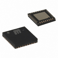
SY89546UMI Micrel Inc, SY89546UMI Datasheet - Page 5

SY89546UMI
Manufacturer Part Number
SY89546UMI
Description
IC MUX 4:1 LVDS DIFF 2.5V 32MLF
Manufacturer
Micrel Inc
Series
SY89r
Type
Multiplexerr
Datasheet
1.SY89546UMG.pdf
(10 pages)
Specifications of SY89546UMI
Circuit
1 x 4:1
Independent Circuits
1
Voltage Supply Source
Single Supply
Voltage - Supply
3 V ~ 3.6 V
Operating Temperature
-40°C ~ 85°C
Mounting Type
Surface Mount
Package / Case
32-MLF®, QFN
Lead Free Status / RoHS Status
Contains lead / RoHS non-compliant
Current - Output High, Low
-
Micrel, Inc.
V
Symbol
f
t
t
t
Crosstalk
t
Notes:
10. Measured with 100mV input swing. See “Timing Diagrams” section for definition of parameters. High frequency AC parameters are guaranteed by
11. Input-to-input skew is the difference in time from an input-to-output in comparison to any other input-to-output. In addition, the input-to-input skew
12. Output-to-output skew is measured between two different outputs under identical input transitions.
13. Part-to-part skew is defined for two parts with identical power supply voltages at the same temperature and with no skew of the edges at the
14. Random jitter is measured with a K28.7 comma detect character pattern, measured at 1.25Gbps and 3.2Gbps.
15. Deterministic jitter is measured at 1.25Gbps and 3.2Gbps, with both K28.5 and 2
16. Total jitter definition: with an ideal clock input of frequency ≤ f
17. Cycle-to-cycle jitter definition: the variation of periods between adjacent cycles, T
18. Crosstalk is measured at the output while applying two similar clock frequencies to adjacent inputs that are asynchronous with respect to each other
M9999-060308
hbwhelp@micrel.com or (408) 955-1690
MAX
pd
SKEW
JITTER
r
, t
CC
AC ELECTRICAL CHARACTERISTICS
f
design and characterization.
does not include the output skew.
respective inputs. Total skew is calculated as the RMS (Root Mean Square) of the input skew and output skew.
specified peak-to-peak jitter value.
signal.
at the inputs.
= 2.5V ±5%; T
Parameter
Maximum Operating Frequency
Differential Propagation Delay
Data
Clock
Crosstalk-Induced Jitter
Output Rise / Fall Time
(20% to 80%)
A
= –40°C to +85°C; R
Deterministic Jitter (DJ)
Output-to-Output Skew
Cycle-to-Cycle Jitter
Input-to-Input Skew
Random Jitter (RJ)
Part-to-Part Skew
Total Jitter (TJ)
L
= 100Ω across Q and /Q, unless otherwise stated.
Condition
V
IN-to-Q
SEL-to-Q
Note 11
Note 12
Note 13
Note 14
Note 15
Note 16
Note 17
Note 18
At full output swing
OUT
(10)
MAX
≥ 200mV
, no more than one output edge in 10
5
23
n
-T
–1 PRBS pattern.
n-1
where T is the time between rising edges of the output
NRZ Data
Clock
12
output edges will deviate by more than the
Min
330
200
3.2
35
Typ
430
400
80
4
4
8
Precision Edge
Max
530
700
200
150
0.7
20
20
10
10
1
1
SY89546U
ps
ps
ps
Units
Gbps
ps
ps
GHz
ps
ps
ps
ps
ps
ps
RMS
RMS
RMS
PP
PP
®


