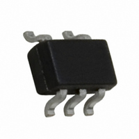
NC7SZ14P5 Fairchild Semiconductor, NC7SZ14P5 Datasheet - Page 5

NC7SZ14P5
Manufacturer Part Number
NC7SZ14P5
Description
IC INVERTER UHS SCHMITT SC70-5
Manufacturer
Fairchild Semiconductor
Series
7SZr
Specifications of NC7SZ14P5
Logic Type
Inverter with Schmitt Trigger
Number Of Inputs
1
Number Of Circuits
1
Current - Output High, Low
32mA, 32mA
Voltage - Supply
1.65 V ~ 5.5 V
Operating Temperature
-40°C ~ 85°C
Mounting Type
Surface Mount
Package / Case
SC-70-5, SC-88A, SOT-323-5, SOT-353, 5-TSSOP
Logical Function
Inverter Schmit Trig
Logic Family
TinyLogic UHS
Number Of Elements
1
Input Type
Schmitt Trigger
High Level Output Current
-32mA
Low Level Output Current
32mA
Propagation Delay Time
15.6ns
Operating Supply Voltage (typ)
1.8/2.5/3.3/5V
Package Type
SC-70
Operating Temp Range
-40C to 85C
Pin Count
5
Quiescent Current
1uA
Output Type
Schmitt Trigger
Technology
CMOS
Mounting
Surface Mount
Operating Temperature Classification
Industrial
Operating Supply Voltage (max)
5.5V
Operating Supply Voltage (min)
1.65V
Lead Free Status / RoHS Status
Lead free / RoHS Compliant
Available stocks
Company
Part Number
Manufacturer
Quantity
Price
Company:
Part Number:
NC7SZ14P5X
Manufacturer:
MICRON
Quantity:
1 001
Company:
Part Number:
NC7SZ14P5X
Manufacturer:
FSC
Quantity:
465 000
Part Number:
NC7SZ14P5X
Manufacturer:
FSC
Quantity:
20 000
Part Number:
NC7SZ14P5X NL
Manufacturer:
FAIRCHILD/仙童
Quantity:
20 000
Part Number:
NC7SZ14P5X-NL
Manufacturer:
FAIRCHILD/仙童
Quantity:
20 000
Part Number:
NC7SZ14P5X_NL
Manufacturer:
FAIRCHILD/仙童
Quantity:
20 000
© 1996 Fairchild Semiconductor Corporation
NC7SZ14 • Rev. 1.0.3
AC Electrical Characteristics
Note:
2.
Note:
3.
Note:
4.
Symbol
t
PLH
C
C
C
current consumption (I
operating current by the expression: I
C
Input PRR=1.0MHz; t
Input=AC Waveform; t
, t
PD
IN
PD
L
PHL
includes load and stray capacitance;
is defined as the value of the internal equivalent capacitance which is derived from dynamic operating
Propagation Delay
Input Capacitance
Power Dissipation
Capacitance
Figure 4. AC Test Circuit
Parameter
(2)
W
r
CCD
=500ns
=t
f
=1.8ns; PRR=10MHz; Duty Cycle =50%.
) at no output loading and operating at 50% duty cycle. C
2.50 ± 0.20
3.30 ± 0.30
5.00 ± 0.50
3.30 ± 0.30
5.00 ± 0.50
V
CC
1.65
1.80
0.00
3.30
5.00
(V)
CCD
Figure 6. I
=(C
C
R
C
R
Conditions
PD
L
L
L
L
=15pF,
=1MΩ
=50pF,
=500Ω
)(V
CC
)(f
CCD
5
IN
)+(I
Test Circuit
Min. Typ.
2.0
2.0
1.0
1.0
0.5
1.5
0.8
CC
static).
T
A
=+25°C
9.1
7.6
5.0
3.7
3.1
4.4
3.7
24
30
4
Figure 5. AC Waveforms
Max.
15.0
12.5
9.0
6.3
5.2
7.2
5.9
Min.
T
2.0
2.0
1.0
1.0
0.5
1.5
0.8
A
PD
+85°C
=-40 to
is related to I
Max.
15.6
13.0
9.5
6.5
5.5
7.5
6.2
Units
ns
pF
CCD
www.fairchildsemi.com
dynamic
Figure 4
Figure 5
Figure 4
Figure 5
Figure 6
Figure


