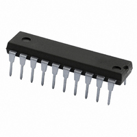
74HC240N,652 NXP Semiconductors, 74HC240N,652 Datasheet - Page 2

74HC240N,652
Manufacturer Part Number
74HC240N,652
Description
IC INVERTER DUAL 4-INPUT 20DIP
Manufacturer
NXP Semiconductors
Series
74HCr
Datasheet
1.74HCT240N652.pdf
(18 pages)
Specifications of 74HC240N,652
Package / Case
20-DIP (0.300", 7.62mm)
Logic Type
Inverter
Number Of Inputs
4
Number Of Circuits
2
Current - Output High, Low
7.8mA, 7.8mA
Voltage - Supply
2 V ~ 6 V
Operating Temperature
-40°C ~ 125°C
Mounting Type
Through Hole
Logic Family
HC
Number Of Channels Per Chip
8
Polarity
Inverting
Supply Voltage (max)
6 V
Supply Voltage (min)
2 V
Maximum Operating Temperature
+ 125 C
Mounting Style
Through Hole
High Level Output Current
- 7.8 mA
Low Level Output Current
7.8 mA
Maximum Power Dissipation
750 mW
Minimum Operating Temperature
- 40 C
Output Current
35 mA
Output Type
3-State
Propagation Delay Time
100 ns @ 2 V or 20 ns @ 4.5 V or 17 ns @ 6 V
Number Of Lines (input / Output)
8 / 8
Lead Free Status / RoHS Status
Lead free / RoHS Compliant
Lead Free Status / RoHS Status
Lead free / RoHS Compliant, Lead free / RoHS Compliant
Other names
568-2649-5
933670520652
933670520652
NXP Semiconductors
Table 1.
4. Functional diagram
74HC_HCT240_3
Product data sheet
Type number
74HCT240D
74HCT240DB
74HCT240PW
74HCT240BQ
Fig 1. Logic symbol
17
15
13
11
19
2
4
6
8
1
1OE
2OE
1A0
2A0
1A1
2A1
1A2
2A2
1A3
2A3
Ordering information
Package
Temperature range Name
40 C to +125 C
40 C to +125 C
40 C to +125 C
40 C to +125 C
1Y0
2Y0
1Y1
2Y1
1Y2
2Y2
1Y3
2Y3
mgu779
18
16
14
12
3
5
7
9
…continued
Fig 2. IEC logic symbol
SO20
SSOP20
TSSOP20
DHVQFN20 plastic dual-in-line compatible thermal enhanced
19
11
13
15
17
Rev. 03 — 2 August 2007
1
2
4
6
8
EN
EN
Description
plastic small outline package; 20 leads;
body width 7.5 mm
plastic shrink small outline package; 20 leads;
body width 5.3 mm
plastic thin shrink small outline package; 20 leads;
body width 4.4 mm
very thin quad flat package; no leads; 20 terminals;
body 2.5
mgu778
4.5
18
16
14
12
9
7
5
3
0.85 mm
74HC240; 74HCT240
Octal buffer/line driver; 3-state; inverting
Fig 3. Functional diagram
17
15
13
11
19
2
4
6
8
1
1OE
1A0
1A1
1A2
1A3
2OE
2A0
2A1
2A2
2A3
© NXP B.V. 2007. All rights reserved.
Version
SOT163-1
SOT339-1
SOT360-1
SOT764-1
mgu780
1Y0
1Y1
1Y2
1Y3
2Y0
2Y1
2Y2
2Y3
18
16
14
12
3
5
7
9
2 of 18


