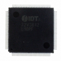
IDT72V3642L10PF IDT, Integrated Device Technology Inc, IDT72V3642L10PF Datasheet - Page 2

IDT72V3642L10PF
Manufacturer Part Number
IDT72V3642L10PF
Description
IC FIFO SYNC 3.3V CMOS 120-TQFP
Manufacturer
IDT, Integrated Device Technology Inc
Series
72Vr
Datasheet
1.IDT72V3642L10PF.pdf
(29 pages)
Specifications of IDT72V3642L10PF
Function
Synchronous
Memory Size
72M (1M x 72)
Data Rate
100MHz
Access Time
10ns
Voltage - Supply
3 V ~ 3.6 V
Operating Temperature
0°C ~ 70°C
Mounting Type
Surface Mount
Package / Case
120-TQFP, 120-VQFP
Lead Free Status / RoHS Status
Contains lead / RoHS non-compliant
Other names
72V3642L10PF
800-1534
800-1534
Available stocks
Company
Part Number
Manufacturer
Quantity
Price
Company:
Part Number:
IDT72V3642L10PF
Manufacturer:
IDT, Integrated Device Technology Inc
Quantity:
10 000
Company:
Part Number:
IDT72V3642L10PF8
Manufacturer:
IDT, Integrated Device Technology Inc
Quantity:
10 000
DESCRIPTION (CONTINUED)
PIN CONFIGURATION
*
NOTES:
1. NC – no internal connection
2. Uses Yamaichi socket IC51-1324-828
board each chip buffer data in opposite directions. Communication between
each port may bypass the FIFOs via two 36-bit mailbox registers. Each mailbox
register has a flag to signal when new mail has been stored.
employs a synchronous interface. All data transfers through a port are gated
to the LOW-to-HIGH transition of a port clock by enable signals. The clocks for
each port are independent of one another and can be asynchronous or
coincident. The enables for each port are arranged to provide a simple
bidirectional interface between microprocessors and/or buses with synchro-
nous control.
the first word written to an empty FIFO is deposited into the memory array. A
IDT72V3622/72V3632/72V3642 CMOS 3.3V SyncBiFIFO
256 x 36 x 2, 512 x 36 x 2, 1,024 x 36 x 2
Electrical pin 1 in center of beveled edge. Pin 1 identifier in corner.
These devices are a synchronous (clocked) FIFO, meaning each port
These devices have two modes of operation: In the IDT Standard mode,
GND
GND
GND
GND
V
V
B
B
B
B
B
B
B
B
B
B
B
B
B
B
B
B
B
B
B
B
B
B
B
B
NC
NC
NC
CC
CC
35
34
33
32
31
30
29
28
27
26
25
24
23
22
21
20
19
18
17
16
15
14
13
12
18
19
20
21
22
23
24
25
26
27
28
29
30
31
32
33
34
35
36
37
38
39
40
41
42
43
44
45
46
47
48
49
50
PQFP (PQ132-1, order code: PQF)
TM
TOP VIEW
*
2
read operation is required to access that word (along with all other words
residing in memory). In the First Word Fall Through mode (FWFT), the first
long-word (36-bit wide) written to an empty FIFO appears automatically on the
outputs, no read operation required (Nevertheless, accessing subsequent
words does necessitate a formal read request). The state of the FWFT pin
during FIFO operation determines the mode in use.
EFB/ORB) and a combined Full/Input Ready Flag (FFA/IRA and FFB/
IRB). The EF and FF functions are selected in the IDT Standard mode. EF
indicates whether or not the FIFO memory is empty. FF shows whether the
memory is full or not. The IR and OR functions are selected in the First Word
Fall Through mode. IR indicates whether or not the FIFO has available memory
locations. OR shows whether the FIFO has data available for reading or not.
It marks the presence of valid data on the outputs.
Each FIFO has a combined Empty/Output Ready Flag (EFA/ORA and
COMMERCIAL TEMPERATURE RANGE
116
115
114
113
112
111
110
109
108
107
106
105
104
103
102
101
100
99
98
97
96
95
94
93
92
91
90
89
88
87
86
85
84
NC
NC
A
A
A
A
V
A
A
GND
A
A
A
A
A
A
A
FWFT
A
V
A
A
A
A
GND
A
A
A
A
A
V
A
NC
35
34
33
32
CC
31
30
29
28
27
26
25
24
23
22
CC
21
20
19
18
17
16
15
14
13
CC
12
4660 drw 02


