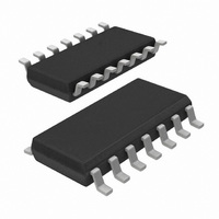
74LV393D,112 NXP Semiconductors, 74LV393D,112 Datasheet - Page 7

74LV393D,112
Manufacturer Part Number
74LV393D,112
Description
IC DUAL 4BIT BINARY RIPPL 14SOIC
Manufacturer
NXP Semiconductors
Series
74LVr
Datasheet
1.74LV393D112.pdf
(12 pages)
Specifications of 74LV393D,112
Package / Case
14-SOIC (3.9mm Width), 14-SOL
Logic Type
Binary Counter
Direction
Up
Number Of Elements
2
Number Of Bits Per Element
4
Reset
Asynchronous
Count Rate
20MHz
Trigger Type
Negative Edge
Voltage - Supply
1 V ~ 3.6 V
Operating Temperature
-40°C ~ 125°C
Mounting Type
Surface Mount
Logic Family
74LV
Number Of Bits
4
Operating Supply Voltage
1 V to 3.6 V
Operating Temperature Range
- 40 C to + 125 C
Mounting Style
SMD/SMT
Lead Free Status / RoHS Status
Lead free / RoHS Compliant
Timing
-
Lead Free Status / Rohs Status
Lead free / RoHS Compliant
Other names
568-2965-5
935162810112
935162810112
Philips Semiconductors
AC WAVEFORMS
V
V
V
output load.
1998 Jun 10
Figure 1. Clock (nCP) to output (1Qn, 2Qn) propagation delays,
M
M
OL
Dual 4-bit binary ripple counter
= 1.5V at V
= 0.5 * V
the clock pulse width, and the maximum clock frequency
and V
nQ
nQ
the master reset to output (Qn) propagation delays,
nMR INPUT
nCP INPUT
n
and the master reset to clock (nCP) removal time
nCP INPUT
n
OUTPUT
OH
OUTPUT
V
Figure 2. Master reset (nMR) pulse width,
V
CC
OH
OL
GND
GND
GND
are the typical output voltage drop that occur with the
V
V
V
V
V
CC
CC
CC
CC
OH
OL
at V
w 2.7V
CC
t 2.7V
V
t
M
PHL
V
M
t
PHL
t
1/f
W
V
M
max
V
M
V
t
M
rem
t
PLH
SV00679
SV00678
7
TEST CIRCUIT
GENERATOR
DEFINITIONS
R
C
R
L
L
T
t
PULSE
PLH/
TEST
= Load resistor
= Load capacitance includes jig and probe capacitance
= Termination resistance should be equal to Z
t
Figure 3. Load circuitry for switching times
PHL
Test Circuit for switching times
V
I
R
2.7–3.6V
< 2.7V
T
V
CC
D.U.T.
V
CC
V
2.7V
V
CC
I
V
O
OUT
C
L
of pulse generators.
Product specification
50pF
74LV393
SV00901
R
L
= 1k


