74LVC245ATTR STMicroelectronics, 74LVC245ATTR Datasheet - Page 4
74LVC245ATTR
Manufacturer Part Number
74LVC245ATTR
Description
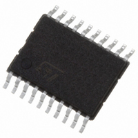
IC TRANSCVR TRI-ST 8BIT 20TSSOP
Manufacturer
STMicroelectronics
Series
74LVCr
Datasheet
1.74LVC245ATTR.pdf
(12 pages)
Specifications of 74LVC245ATTR
Logic Type
Transceiver, Non-Inverting
Number Of Elements
1
Number Of Bits Per Element
8
Current - Output High, Low
24mA, 24mA
Voltage - Supply
1.65 V ~ 3.6 V
Operating Temperature
-55°C ~ 125°C
Mounting Type
Surface Mount
Package / Case
20-TSSOP
Logic Family
74L
Number Of Channels Per Chip
8
Input Level
LVTTL
Output Level
LVTTL
Output Type
3-State
High Level Output Current
- 24 mA
Low Level Output Current
24 mA
Propagation Delay Time
8.8 ns
Supply Voltage (max)
3.6 V
Supply Voltage (min)
1.65 V
Maximum Operating Temperature
+ 125 C
Function
The 74LVC245A is a low voltage CMOS
Input Bias Current (max)
10 uA
Minimum Operating Temperature
- 55 C
Mounting Style
SMD/SMT
Number Of Circuits
8
Polarity
Non-Inverting
Lead Free Status / RoHS Status
Lead free / RoHS Compliant
Other names
497-7105-2
74LVC245ATTR
74LVC245ATTR


74LVC245A
Table 7: Dynamic Switching Characteristics
1) Number of output defined as "n". Measured with "n-1" outputs switching from HIGH to LOW or LOW to HIGH. The remaining output is
measured in the LOW state.
Table 8: AC Electrical Characteristics
1) Skew is defined as the absolute value of the difference between the actual propagation delay for any two outputs of the same device switch-
ing in the same direction, either HIGH or LOW (t
2) Parameter guaranteed by design
Table 9: Capacitive Characteristics
1) C
load. (Refer to Test Circuit). Average operating current can be obtained by the following equation. I
4/12
t
t
t
Symbol
Symbol
Symbol
PLH
PZL
PLZ
t
t
PD
V
V
OSLH
OSHL
C
C
OLP
OLV
PD
is defined as the value of the IC’s internal equivalent capacitance which is calculated from the operating current consumption without
IN
t
t
t
PZH
PHZ
PHL
Dynamic Low Level Quiet
Output (note 1)
Propagation Delay
Time
Output Enable Time 1.65 to 1.95
Output Disable Time 1.65 to 1.95
Output To Output
Skew Time (note1,
2)
Input Capacitance
Power Dissipation Capacitance
(note 1)
Parameter
Parameter
Parameter
1.65 to 1.95
2.3 to 2.7
3.0 to 3.6
2.3 to 2.7
3.0 to 3.6
2.3 to 2.7
3.0 to 3.6
2.7 to 3.6
V
(V)
2.7
2.7
2.7
CC
OSLH
Test Condition
= | t
PLHm
(pF)
V
V
C
(V)
3.3
30
30
50
50
30
30
50
50
30
30
50
50
(V)
1.8
2.5
3.3
CC
CC
L
- t
PLHn
Test Condition
Test Condition
1000
1000
1000
500
500
500
500
500
500
500
500
500
( )
R
|, t
L
V
OSHL
IL
= 0V, V
t
f
s
(ns)
IN
C
2.0
2.0
2.5
2.5
2.0
2.0
2.5
2.5
2.0
2.0
2.5
2.5
= | t
= t
L
= 10MHz
= 50pF
r
PHLm
IH
Min.
= 3.3V
2.0
2.0
1.5
1.0
2.0
2.0
1.0
1.0
2.0
2.0
2.0
2.0
- t
-40 to 85 °C
PHLn
|
CC(opr)
Max.
9.0
8.0
7.3
6.3
9.5
9.0
8.5
9.0
8.5
7.5
12
11
Min.
Min.
1
Value
= C
T
T
PD
A
A
Value
Min.
Value
-55 to 125 °C
= 25 °C
Typ.
2.0
2.0
1.5
1.0
2.0
2.0
1.0
1.0
2.0
2.0
2.0
2.0
= 25 °C
Typ.
x V
-0.8
0.8
28
30
34
4
CC
x f
IN
Max.
Max.
10.5
12.5
Max.
+ I
8.8
7.6
9.0
12
16
10
14
12
10
11
1
CC
/n (per circuit)
Unit
Unit
Unit
pF
pF
ns
ns
ns
ns
V
Related parts for 74LVC245ATTR
Image
Part Number
Description
Manufacturer
Datasheet
Request
R

Part Number:
Description:
IC TRANSCVR TRI-ST DL 24SOIC
Manufacturer:
NXP Semiconductors
Datasheet:

Part Number:
Description:
IC ADDRESS/CLK DRIVER 56-TSSOP
Manufacturer:
IDT, Integrated Device Technology Inc
Datasheet:

Part Number:
Description:
IC MUX/DEMUX 2X1 6TSOP
Manufacturer:
NXP Semiconductors
Datasheet:

Part Number:
Description:
IC SWITCH QUAD SPST 14SOIC
Manufacturer:
NXP Semiconductors
Datasheet:

Part Number:
Description:
IC BUFF DVR TRI-ST 16BIT 48TSSOP
Manufacturer:
IDT, Integrated Device Technology Inc
Datasheet:

Part Number:
Description:
IC BUFF HEX OPEN DRAIN 14TSSOP
Manufacturer:
NXP Semiconductors
Datasheet:
Part Number:
Description:
IC BUFF HEX OPEN DRAIN 14SOICN
Manufacturer:
NXP Semiconductors
Datasheet:
Part Number:
Description:
IC BUFF DVR TRI-ST QD 14SSOP
Manufacturer:
NXP Semiconductors
Datasheet:
Part Number:
Description:
IC BUFF DVR TRI-ST QD 14SOICN
Manufacturer:
NXP Semiconductors
Datasheet:
Part Number:
Description:
IC BUFF DVR TRI-ST QD 14SOICN
Manufacturer:
NXP Semiconductors
Datasheet:
Part Number:
Description:
IC BUFF DVR TRI-ST QD 14SSOP
Manufacturer:
NXP Semiconductors
Datasheet:
Part Number:
Description:
IC BUFF DVR TRI-ST QD 14TSSOP
Manufacturer:
NXP Semiconductors
Datasheet:

Part Number:
Description:
IC BUFF/DVR TRI-ST DUAL 20SSOP
Manufacturer:
NXP Semiconductors
Datasheet:

Part Number:
Description:
IC BUFF/DVR TRI-ST DUAL 20SOIC
Manufacturer:
NXP Semiconductors
Datasheet:

Part Number:
Description:
IC BUFF/DVR TRI-ST DUAL 20TSSOP
Manufacturer:
NXP Semiconductors
Datasheet: