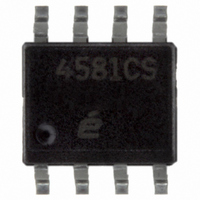
EL4581CS Intersil, EL4581CS Datasheet - Page 8

EL4581CS
Manufacturer Part Number
EL4581CS
Description
IC VIDEO SYNC SEPARATOR 8-SOIC
Manufacturer
Intersil
Type
Synchronous Separatorr
Datasheet
1.EL4581CSZ-T7.pdf
(10 pages)
Specifications of EL4581CS
Applications
Multimedia Displays, Test Equipment
Mounting Type
Surface Mount
Package / Case
8-SOIC (3.9mm Width)
Lead Free Status / RoHS Status
Contains lead / RoHS non-compliant
Available stocks
Company
Part Number
Manufacturer
Quantity
Price
Part Number:
EL4581CS
Manufacturer:
ELANTEC
Quantity:
20 000
Company:
Part Number:
EL4581CS-T7
Manufacturer:
ATI
Quantity:
41
Part Number:
EL4581CS-T7
Manufacturer:
ELANTEC
Quantity:
20 000
Company:
Part Number:
EL4581CSZ
Manufacturer:
Intersil
Quantity:
1 387
Part Number:
EL4581CSZ
Manufacturer:
INTERSIL
Quantity:
20 000
Company:
Part Number:
EL4581CSZ-T7
Manufacturer:
Intersil
Quantity:
4 000
fixed level above the clamp voltage V
initiates the timing one-shots for gating the sample and hold
circuits. The sample of the sync tip is delayed by 0.8µs to
enable the actual sample of 2µs to be taken on the optimum
section of the sync. pulse tip. The acquisition time of the
circuit is about three horizontal lines. The double poly CMOS
technology enables long time constants to be achieved with
small high quality on-chip capacitors. The back porch
voltage is similarly derived from the trailing edge of sync,
which also serves to cut off the tip sample if the gate time
exceeds the tip period. Note that the sample and hold gating
times will track RSET through I
The 50% level of the sync tip is derived, through the resistor
divider R
and V
This comparator has built in hysteresis to avoid false
triggering. The output of C2 is a digital 5V signal which feeds
the C/S output buffer B1 and the other internal circuit blocks,
the vertical, back porch and odd/even functions.
The vertical circuit senses the C/S edges and initiates an
integrator which is reset by the shorter horizontal sync
pulses but times out the longer vertical sync. pulse widths.
Block Diagram
BP
, and applied to the plus input of comparator C1.
1
and R
2
, from the sample and held voltages V
8
OT
C SYNC OUT
C
VERTICAL
VIDEO IN
1
.
OUT
GND
1
2
3
4
R1
FIGURE 13. STANDARD (NTSC INPUT) H. SYNC DETAIL
V
. The output of C2
R1
V
I
1
R2
D2
B1
3-POLE FILTER
F1
CLAMP
C2
A1
I
OT
I
OT
VERTICAL
DETECT
I
S/H
OT
TIP
VBP
VTIP
V
EL4581
R3
R2
R1
-
+
C1
V
V
V
R1
R2
R3
CS
The internal timing circuits are referenced to I
the time-out period being inversely proportional to the timing
current. The vertical output pulse is started on the first
serration pulse in the vertical interval and is then self-timed
out. In the absence of a serration pulse, an internal timer will
default the start of vertical.
The back porch is triggered from the sync tip trailing edge
and initiates a one-shot pulse. The period of this pulse is
again a function of I
set by R
The odd/even circuit (O/E) comprises of flip flops which track
the relationship of the horizontal pulses to the leading edge
of the vertical output, and will switch on every field at the
start of vertical. Pin 7 is high during the odd field.
Loss of video signal can be detected by monitoring the C/S
output. The 50% level of the previous video signal will
remain held on the S/H capacitors after the input video
signal has gone and the input on pin 2 has defaulted to the
clamp voltage. Consequently, the C/S output will remain low
longer than the normal vertical pulse period. An external
timing circuit could be used to detect this condition.
DETECT
V
PORCH
BACK
REF
I
OT
I
OT
V
V
SET
DETECT
R4
R3
O/E
+
-
.
A2
V
I
REF
DD
B3
B4
OT
I
TR
Q1
BURST/BACK
PORCH OUT
ODD/EVEN
R3
and will therefore track the scan rate
RSET
OUT
RSET
V
8
7
6
5
DD
*NOTE:
RSET MUST BE A
1% RESISTOR.
OT
November 12, 2010
and V
FN7172.2
R3
,


