LMH1980MM/NOPB National Semiconductor, LMH1980MM/NOPB Datasheet - Page 9
LMH1980MM/NOPB
Manufacturer Part Number
LMH1980MM/NOPB
Description
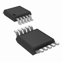
IC SEPARATOR VID SD/HD/PC 10MSOP
Manufacturer
National Semiconductor
Type
Video Syncr
Datasheet
1.LMH1980MMNOPB.pdf
(14 pages)
Specifications of LMH1980MM/NOPB
Applications
Displays, Projectors, Receivers
Mounting Type
Surface Mount
Package / Case
10-MSOP, Micro10™, 10-uMAX, 10-uSOP
Supply Voltage (max)
5 V
Supply Voltage (min)
3.3 V
Maximum Operating Temperature
+ 85 C
Minimum Operating Temperature
- 40 C
Mounting Style
SMD/SMT
Lead Free Status / RoHS Status
Lead free / RoHS Compliant
Other names
LMH1980MMTR
Available stocks
Company
Part Number
Manufacturer
Quantity
Price
Company:

Part Number:
LMH1980MM/NOPB
Manufacturer:
TI
Quantity:
1 746


Application Information
GENERAL DESCRIPTION
The LMH1980 is designed to extract the timing information
from various video formats with standard and non-standard
vertical serration and output the syncs and relevant timing
signals in CMOS logic. Its advanced features and easy ap-
plication make it ideal for consumer, professional, and indus-
trial video systems where sync timing needs to be extracted
from SD, HD, and PC video signals. The device can operate
from a supply voltage between 3.3V and 5V. The only re-
quired external components are bypass capacitors between
the V
signal source to the V
resistor between the R
circuit in Figure 2.
R
The precision external resistor (R
bias current and precise reference voltage for the LMH1980.
For optimal performance, R
sion resistor with a low temperature coefficient to ensure
proper operation over a wide temperature range. Using a
R
formance (like worse performance, increased propagation
delay variation, or reduced input sync amplitude range)
against temperature, supply voltage, input signal, or part-to-
part variations.
Note: The R
ferent function than the “R
ous sync separators, like the LM1881. For the LM1881, the
R
ferent input line rates. For the LMH1980, the R
fixed, and the device automatically detects the input line rate
to support various video formats without electrical or physical
intervention.
Automatic Format Detection and Switching
Automatic format detection eliminates the need for adjusting
an external R
troller. The device outputs will respond correctly to a switch
in video format after a sufficient start-up time has been satis-
fied, usually within 1 to 2 fields of video. Unlike other sync
separators, the LMH1980 does not require the power to be
cycled in order to produce correct outputs after a significant
change to the input signal. See the Start-up Time section for
more details.
Fixed-Level Sync Slicing
The LMH1980 uses fixed-level sync slicing for video inputs
with an amplitude from 0.5V
er sync separation even for improperly terminated or attenu-
ated input signals. The fixed-level sync slicing threshold is
nominally 70 mV above the clamped sync tip. This means that
for a minimum video input signal amplitude of 0.5V
slicing level is near the mid-point of the sync pulse amplitude.
This slicing level is independent of the input signal amplitude;
therefore, for a 2V
the sync pulse amplitude.
EXT
EXT
SET
CC
Resistor
resistor with less precision may result in reduced per-
value needed to be adjusted externally to support dif-
and GND pins, input coupling capacitor (C
EXT
SET
resistor used with the LMH1980 serves a dif-
resistor or programming via a microcon-
PP
input, the slicing level occurs at 12% of
IN
EXT
pin, and a fixed-value 1% precision
SET
and GND pins. Refer to the test
PP
EXT
resistor” used with other previ-
to 2V
should be a 10 kΩ 1% preci-
EXT
PP
) establishes the internal
, which allows for prop-
EXT
IN
) from the
value is
PP
, the
9
INPUT CONSIDERATIONS
The LMH1980 supports sync separation for analog CVBS, Y
(luma) from Y/C and YP
GBR/RGsB, as specified in the following video standards.
•
•
•
•
Input Termination
The video source should be load terminated with a 75Ω re-
sistor to ensure correct video signal amplitude and minimize
signal distortion due to reflections. In extreme cases, the
LMH1980 can handle non-terminated or double-terminated
input conditions, assuming 1V
terminated video.
Input Filtering
An external filter is recommended if the video signal has large
chroma amplitude that extends near the sync tip and/or has
considerable high-frequency noise, so they do not interfere
with sync separation. A simple RC low-pass chroma filter with
a series resistor (R
be used to sufficiently attenuate chroma such that minimum
peak of its amplitude is above the slicing level and also to
improve the overall signal-to-noise ratio. To achieve the de-
sired filter cutoff frequency, it’s advised to vary C
R
voltage drop across R
quency decreases, the LMH1980 output propagation delays
increase, which could affect the timing relationship between
the sync and video signals.
In applications where the chroma filter needs to be disabled
when HD video is input, it is possible to use a transistor switch
(Q1) controlled by the HD flag (pin 5) to open C
to ground as shown in Figure 11. When a HD tri-level sync
input signal is applied, HD will output logic low (following a
brief delay for auto format detection) and Q1 will turn off to
disable the chroma filter, which is intended for SD composite
video only. When a SD bi-level sync signal (i.e.: NTSC/PAL)
is applied, HD will output logic high and Q1 will turn on to
enable the chroma filter.
Important: If the filter cutoff frequency (f
HD video is applied, the filter can severely roll off and atten-
uate the input's high-bandwidth tri-level sync pulses such that
the LMH1980 cannot detect a valid HD input signal. If the
LMH1980 cannot detect a valid HD input, then the HD flag will
never change from logic high to low and the switch-controlled
filter will never be disabled via Q1. In other words, f
not be set too low that the filter impairs the LMH1980's ability
to detect a valid HD input. The values of R
Figure 11 give f
subcarrier frequency) without impairing HD video format de-
tection.
9
Composite Video (CVBS) and S-Video (Y/C):
— SMPTE 170M (NTSC), ITU-R BT.470 (PAL)
Component Video (YP
— SDTV: SMPTE 125M, SMPTE 267M, ITU-R BT.601
— EDTV: ITU-R BT.1358 (480P, 576P)
— HDTV: SMPTE 296M (720P), SMPTE 274M
PC Graphics (RGsB):
— VESA Monitor Timing Standards and Guidelines
Non-Standard Video:
— Composite NTSC & PAL (or Component 480I & 576I)
small (i.e.: 100Ω) to minimize sync tip clipping due to the
(480I, 576I)
(1080I/P), SMPTE RP 211 (1080PsF)
Version 1.0, Revision 0.8
without vertical serration & equalization pulses (i.e.:
from logical OR-ing of H & V signals)
CO
=2.79 MHz (about -4 dB at 3.58 MHz NTSC
9
) and a filter capacitor (C
9
. Keep in mind that as the cutoff fre-
B
B
P
P
R
R
, and G (sync on green) from
PP
/GBR):
signal amplitude for normally
CO
) is set too low and
9
and C
2
) to ground can
2
’s connection
www.national.com
2
2
CO
and keep
shown in
should
Related parts for LMH1980MM/NOPB
Image
Part Number
Description
Manufacturer
Datasheet
Request
R

Part Number:
Description:
Manufacturer:
National Semiconductor
Datasheet:

Part Number:
Description:
Auto-detecting Sd/hd/pc Video Sync Separator
Manufacturer:
National Semiconductor Corporation
Datasheet:
Part Number:
Description:
National Semiconductor [8-Bit D/A Converter]
Manufacturer:
National Semiconductor
Datasheet:
Part Number:
Description:
National Semiconductor [Media Coprocessor]
Manufacturer:
National Semiconductor
Datasheet:
Part Number:
Description:
Digitally Controlled Tone and Volume Circuit with Stereo Audio Power Amplifier, Microphone Preamp Stage and National 3D Sound
Manufacturer:
National Semiconductor
Datasheet:
Part Number:
Description:
Digitally Controlled Tone and Volume Circuit with Stereo Audio Power Amplifier, Microphone Preamp Stage and National 3D Sound
Manufacturer:
National Semiconductor
Datasheet:
Part Number:
Description:
AC97 Rev 2 Codec with Sample Rate Conversion and National 3D Sound
Manufacturer:
National Semiconductor
Part Number:
Description:
Manufacturer:
National Semiconductor
Datasheet:
Part Number:
Description:
Manufacturer:
National Semiconductor
Datasheet:
Part Number:
Description:
General Purpose, Low Voltage, Low Power, Rail-to-Rail Output Operational Amplifiers
Manufacturer:
National Semiconductor
Datasheet:
Part Number:
Description:
8-bit 20 MSPS flash A/D converter.
Manufacturer:
National Semiconductor
Datasheet:
Part Number:
Description:
Low Noise Quad Operational Amplifier
Manufacturer:
National Semiconductor
Datasheet:
Part Number:
Description:
Quad Differential Line Receivers
Manufacturer:
National Semiconductor
Datasheet:
Part Number:
Description:
Quad High Speed Trapezoidal? Bus Transceiver
Manufacturer:
National Semiconductor
Datasheet: