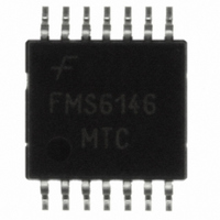
FMS6146MTC14X Fairchild Semiconductor, FMS6146MTC14X Datasheet - Page 9

FMS6146MTC14X
Manufacturer Part Number
FMS6146MTC14X
Description
IC DRIVER VIDEO FLTR 6CH 14TSSOP
Manufacturer
Fairchild Semiconductor
Type
Driverr
Datasheet
1.FMS6146MTC14X.pdf
(11 pages)
Specifications of FMS6146MTC14X
Applications
Recorders, Set-Top Boxes
Mounting Type
Surface Mount
Package / Case
14-TSSOP
Lead Free Status / RoHS Status
Lead free / RoHS Compliant
Other names
FMS6146MTC14XTR
FMS6146MTC14X_NL
FMS6146MTC14X_NLTR
FMS6146MTC14X_NLTR
FMS6146MTC14X_NL
FMS6146MTC14X_NLTR
FMS6146MTC14X_NLTR
Available stocks
Company
Part Number
Manufacturer
Quantity
Price
Part Number:
FMS6146MTC14X
Manufacturer:
FAIRCHILD/仙童
Quantity:
20 000
© 2006 Fairchild Semiconductor Corporation
FMS6146 • Rev. 1.1.0
Layout Considerations
General layout and supply bypassing play major roles in
high-frequency performance and thermal characteristics.
Fairchild offers a demonstration board, FMS6146DEMO,
to guide layout and aid device testing and characterizati-
on. The FMS6146DEMO is a four-layer board with full
power and ground planes. Following this layout confi gu-
ration provides the optimum performance and thermal
characteristics. For optimum results, follow the guidelines
below as a basis for high-frequency layout:
■
■
■
■
■
■
Place the 0.1μF capacitor within 0.1 inches of the
For multi-layer boards, use a large ground plane to help
For two-layer boards, use a ground plane that extends
Include 1μF and 0.1μF ceramic bypass capacitors.
Place the 1μF capacitor within 0.75 inches of the
power pin.
power pin.
dissipate heat.
beyond the device by at least 0.5 inches.
Minimize all trace lengths to reduce series inductances.
9
Output Considerations
The FMS6146 outputs are DC offset from the input by
150mV. Therefore, V
required to obtain optimal performance from the output dri-
ver and is held at the minimum value to decrease the stan-
ding DC current into the load. Since the FMS6146 has a 2x
(6dB) gain, the output is typically connected via a 75Ω-
series back-matching resistor, followed by the 75Ω video
cable. Due to the inherent divide by two of this confi gurati-
on, the blanking level at the load of the video signal is
always less than 1V. When AC-coupling the output, ensure
that the coupling capacitor of choice passes the lowest
frequency content in the video signal and that line time dis-
tortion (video tilt) is kept as low as possible.
The selection of the coupling capacitor is a function of the
subsequent circuit input impedance and the leakage cur-
rent of the input being driven. To obtain the highest quality
output video signal, the series termination resistor must be
placed as close to the output pin as possible. This reduces
the parasitic capacitance and inductance effect on the out-
put driver. The distance from the device pin to the series
termination resistor should be no greater than 0.1 inches.
Figure 16. Distance from Device Pin to Series
Termination Resistor
OUT
= 2•V
IN
DC+150mV. This offset is
www.fairchildsemi.com


