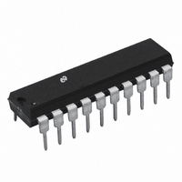
LM1972N National Semiconductor, LM1972N Datasheet - Page 8

LM1972N
Manufacturer Part Number
LM1972N
Description
IC AUDIO ATTENUATOR 2CH 20-DIP
Manufacturer
National Semiconductor
Type
Audio Attenuatorr
Datasheet
1.LM1972MNOPB.pdf
(12 pages)
Specifications of LM1972N
Applications
Consoles, MIDI
Mounting Type
Through Hole
Package / Case
20-DIP (0.300", 7.62mm)
Attenuator Step Size
0.5/1dB
Number Of Bits
16
Number Of Channels
2
Power Dissipation
150mW
Supply Current
4mA
Operating Temperature (min)
0C
Operating Temperature (max)
70C
Operating Temperature Classification
Commercial
Lead Free Status / RoHS Status
Contains lead / RoHS non-compliant
Other names
*LM1972N
www.national.com
μPot LADDER ARCHITECTURE
Each channel of a μPot has its own independent resistor lad-
der network. As shown in Figure 8, the ladder consists of
multiple R1/R2 elements which make up the attenuation
scheme. Within each element there are tap switches that se-
DIGITAL LINE COMPATIBILITY
The μPot's digital interface section is compatible with either
TTL or CMOS logic due to the shift register inputs acting upon
a threshold voltage of 2 diode drops or approximately 1.4V.
DIGITAL DATA-OUT PIN
The DATA-OUT pin is available for daisy-chain system con-
figurations where multiple μPots will be used. The use of the
daisy-chain configuration allows the system designer to use
DAISY-CHAIN CAPABILITY
Since the μPot's digital interface is essentially a shift register,
multiple μPots can be programmed utilizing the same data
and load/shift lines. As shown in Figure 11, for an n-μPot
daisy-chain, there are 16n bits to be shifted and loaded for the
chain. The data loading sequence is the same for n-μPots as
it is for one μPot. First the LOAD/SHIFT line goes low, then
the data is clocked in sequentially while the preceding data in
each μPot is shifted out the DATA-OUT pin to the next μPot
in the chain or to ground if it is the last μPot in the chain. Then
FIGURE 9. μPot System Architecture
FIGURE 8. μPot Ladder Architecture
8
lect the appropriate attenuation level corresponding to the
data bits in Table 1. It can be seen in Figure 8 that the input
impedance for the channel is a constant value regardless of
which tap switch is selected, while the output impedance
varies according to the tap switch selected.
only one DATA and one LOAD/SHIFT line per chain, thus
simplifying PCB trace layouts.
In order to provide the highest level of channel separation and
isolate any of the signal lines from digital noise, the DATA-
OUT pin should be terminated through a 2 kΩ resistor if not
used. The pin may be left floating, however, any signal noise
on that line may couple to adjacent lines creating higher noise
specs.
the LOAD/SHIFT line goes high; latching the data into each
of their corresponding μPots. The data is then decoded ac-
cording to the address (channel selection) and the appropri-
ate tap switch controlling the attenuation level is selected.
CROSSTALK MEASUREMENTS
The crosstalk of a μPot as shown in the Typical Performance
Characteristics section was obtained by placing a signal on
one channel and measuring the level at the output of another
channel of the same frequency. It is important to be sure that
1197812
1197811


