AD632ADZ Analog Devices Inc, AD632ADZ Datasheet - Page 5
AD632ADZ
Manufacturer Part Number
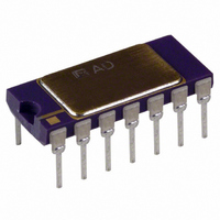
AD632ADZ
Description
IC MULTIPLIER MONO PREC 14-CDIP
Manufacturer
Analog Devices Inc
Specifications of AD632ADZ
Function
Analog Multiplier/Divider
Number Of Bits/stages
4-Quadrant
Package / Case
14-CDIP (0.300", 7.62mm)
No. Of Multipliers / Dividers
1
No. Of Amplifiers
4
Supply Voltage Range
± 8V To ± 18V
Slew Rate
20V/µs
Operating Temperature Range
-25°C To +85°C
Digital Ic Case Style
TO-116
Lead Free Status / RoHS Status
Lead free / RoHS Compliant
Lead Free Status / RoHS Status
Lead free / RoHS Compliant, Lead free / RoHS Compliant
Available stocks
Company
Part Number
Manufacturer
Quantity
Price
Company:

Part Number:
AD632ADZ
Manufacturer:
Analog Devices Inc
Quantity:
135


Rev. B
Feedback attenuation also retains the capability for adding a
signal to the output. Signals may be applied to the Z terminal,
where they are amplified by –10, or to the common ground
connection where they are amplified by –1. Input signals may
also be applied to the lower end of the 2.7 k resistor, giving a
gain of +9.
OPERATION AS A DIVIDER
Figure 7 shows the connection required for division. Unlike
earlier products, the AD632 provides differential operation on
both numerator and denominator, allowing the ratio of two
floating variables to be generated. Further flexibility results from
access to a high impedance summing input to Y
dividers based on the use of a multiplier in a feedback loop, the
bandwidth is proportional to the denominator magnitude, as
shown in Figure 3.
Figure 6. Connections for Scale-Factor of Unity
Figure 7. Basic Divider Connection
1
. As with all
–5–
Without additional trimming, the accuracy of the AD632B is
sufficient to maintain a 1% error over a 10 V to 1 V denomina-
tor range (The AD535 is functionally equivalent to the AD632
and has guaranteed performance in the divider and square-rooter
configurations and is recommended for such applications).
This range may be extended to 100:1 by simply reducing the X
offset with an externally generated trim voltage (range required
is ± 3.5 mV max) applied to the unused X input. To trim, apply
a ramp of +100 mV to +V at 100 Hz to both X
used for offset adjustment, otherwise reverse the signal polarity)
and adjust the trim voltage to minimize the variation in the
output.*
Since the output will be near +10 V, it should be ac-coupled for
this adjustment. The increase in noise level and reduction in
bandwidth preclude operation much beyond a ratio of 100 to 1.
*See the AD535 data sheet for more details.
1
and Z
AD632
1
(if X
2
is
Related parts for AD632ADZ
Image
Part Number
Description
Manufacturer
Datasheet
Request
R

Part Number:
Description:
±1.7g Dual-Axis IMEMS Accelerometer Evaluation Board
Manufacturer:
Analog Devices Inc
Datasheet:

Part Number:
Description:
Inertial Sensor Evaluation System
Manufacturer:
Analog Devices Inc
Datasheet:
Part Number:
Description:
Manufacturer:
Analog Devices Inc
Datasheet:
Part Number:
Description:
Manufacturer:
Analog Devices Inc
Datasheet:
Part Number:
Description:
Manufacturer:
Analog Devices Inc
Datasheet:
Part Number:
Description:
Manufacturer:
Analog Devices Inc
Datasheet:
Part Number:
Description:
Manufacturer:
Analog Devices Inc
Datasheet:
Part Number:
Description:
Manufacturer:
Analog Devices Inc
Datasheet:
Part Number:
Description:
Manufacturer:
Analog Devices Inc
Datasheet:
Part Number:
Description:
Manufacturer:
Analog Devices Inc
Datasheet:
Part Number:
Description:
Manufacturer:
Analog Devices Inc
Datasheet:
Part Number:
Description:
Manufacturer:
Analog Devices Inc
Datasheet:
Part Number:
Description:
Manufacturer:
Analog Devices Inc
Datasheet: