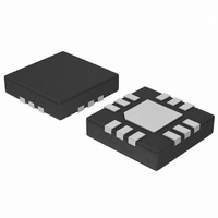
NCP2811AMTTXG ON Semiconductor, NCP2811AMTTXG Datasheet - Page 11

NCP2811AMTTXG
Manufacturer Part Number
NCP2811AMTTXG
Description
IC AMP STEREO HEADPHONE 12WQFN
Manufacturer
ON Semiconductor
Series
NOCAP™r
Type
Class ABr
Datasheet
1.NCP2811AFCT1G.pdf
(14 pages)
Specifications of NCP2811AMTTXG
Features
Depop, Short-Circuit and Thermal Protection, Shutdown
Package / Case
12-VFQFN Exposed Pad
Mounting Type
Surface Mount
Voltage - Supply
2.7 V ~ 5 V
Output Type
Headphones, 2-Channel (Stereo)
Max Output Power X Channels @ Load
110 mW x 2 @ 16 Ohm
Product
General Purpose Audio Amplifiers
Output Power
27 mW
Available Set Gain
- 1.5 V/V
Thd Plus Noise
1 %
Operating Supply Voltage
2.7 V to 5 V
Supply Current
6 mA
Maximum Operating Temperature
+ 85 C
Mounting Style
SMD/SMT
Minimum Operating Temperature
- 40 C
Supply Voltage (max)
+ 6 V
Supply Voltage (min)
- 0.3 V
Lead Free Status / RoHS Status
Lead free / RoHS Compliant
Available stocks
Company
Part Number
Manufacturer
Quantity
Price
Company:
Part Number:
NCP2811AMTTXG
Manufacturer:
ON Semiconductor
Quantity:
1 700
Detailed Descriptions
ground architecture. This architecture eliminates the need to
use 2 external big capacitors required by conventional
headphone amplifier.
true ground amplifiers, an UVLO, a short circuit protection
and also a thermal shutdown. A special circuitry is
embedded to eliminate any pop and click noise that occurs
during turn on and turn off time. The A version has an
external gain selectable by two resistor, B version has a gain
of 1.5 V/V.
NOCAPt
2 small ceramic capacitors. It generates a symmetrical
positive and negative voltage and it allows the output of the
amplifiers to be biased around the ground.
Current Limit Protection Circuit
to ground. When an output is shorted to GND and when a
signal appears at the input, the current is limited to 300 mA.
Thermal Overload Protection
exceed 160°C, and will be switch on again when the
temperature decrease below 140°C.
Under Voltage Lockout
amplifiers are turned off. The hysteresis to turn on it again
is 100 mV.
Pop and Click Suppression Circuitry
pop and click noise during turn on and turn off time. Basic
amplifier creates an offset during these transitions at the
output which give a parasitic noise called “pop and click
noise”. The NCP2811 eliminates this problem.
Gain Setting Resistor Selection (Rin & Rf, A version
only)
gain configuration (close to 1) minimizes the THD + noise
values and maximizes the signal to noise ratio.
to optimize overall system performance.
Input Capacitor Selection
amplifier input terminal. This capacitor creates a high−pass
The NCP2811 is a stereo headphone amplifier with a true
The structure of the NCP2811 is basically composed of 2
NOCAPt is a patented architecture which requires only
The NCP2811 embed a protection circuitry against short
Internal amplifiers are switched off when the temperature
When the battery voltage decreases below 2.3 V, the
The NCP2811 includes a special circuitry to eliminate any
R
A closed loop gain in the range of 1 to 10 is recommended
The formula to calculate the gain is:
The input coupling capacitor blocks the DC voltage at the
in
and R
f
set the closed loop gain of the amplifier. A low
Av + *
R
R
in
f
DETAIL OPERATING DESCRIPTION
http://onsemi.com
11
filter with R
B version).
in low frequencies without severe attenuation in the audio
bandwith (20 Hz – 20 kHz).
Charge Pump Capacitor Selection
performances. X5R / X7R capacitor is recommended.
the generation of the negative voltage.
CFly capacitor to allow maximum transfer charge. The
CPVM value must not exceed 1 mF. Higher capacitor value
can damage the part.
output power is reduced and the device may not operate to
specifications.
Power Supply Decoupling Capacitor (C1)
the adequate decoupling capacitor to reduce noise and
THD+N. Use X5R / X7R ceramic capacitor and place it
closed to the CPVDD pin. A value of 1 mF is recommended.
Shutdown Function
is low. During the shutdown mode, the DC quiescent current
of the circuit does not exceed 500 nA. In this configuration,
the output impedance is 10 kW on each output.
Output Resistor for Capacitive Drive Capability
capacitive load is in the 80 pF range. If, for any reason, high
value capacitive loads should be connected to NCP2811
outputs, an additional 10 W resistor should be placed
between the NCP2811 output and the capacitive load to
ensure amplifier stability.
Layout Recommendation
PVM and PGND to avoid any perturbation due to the
switching.
Table 4.
Value
The size of the capacitor must be large enough to couple
The cut off frequency for the input high−pass filter is:
A F
Use ceramic capacitor with low ESR for better
The flying capacitor (C2) serves to transfer charge during
The CPVM capacitor (C3) must be equal at least to the
Table 4 suggests typical value and manufacturer:
Lower value of capacitors can be used but the maximum
The NCP2811 is a True Ground amplifier which requires
The device enters in shutdown mode when shutdown signal
Under normal operation, NCP2811 maximum direct
Connect C1 as close as possible of the Vp pin.
Connect C2 and C3 as close as possible of the NCP2811.
Route audio signal and AGND far from Vp, CPP, CPM,
1 mF
1 mF
c
< 20 Hz is recommended.
GRM155R60J105K19
in
C1005X5R0J105K
(externally selectable for A version, 20 kW for
Reference
F
c
+
2pR
1
in
Package
C
0402
0402
in
Manufacturer
Murata
TDK


