BA5415A Rohm Semiconductor, BA5415A Datasheet
BA5415A
Specifications of BA5415A
Available stocks


Related parts for BA5415A


BA5415A Summary of contents
Page 1
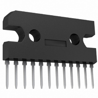
... High-output dual power amplifier BA5415A / BA5416 The BA5415A and BA5416 are dual power amplifier ICs that operate off 15V supply. When driving a 4Ω load off a 9V supply, the BA5415A does not require a heatsink. The BA5416 uses a lost-cost package. The basic characteristics (total harmonic distortion etc ...
Page 2
... Audio ICs ! ! ! ! Block diagram + − Internal circuit configuration 8k 7 Filter 76k 5 BIN 50k I SIN 50k T.S 44k 4/9 NF BA5415A / BA5416 GND + − 3/10 B.S 2/11 OUT GND12 ...
Page 3
... I 0 OFF − − I 0.3 SIN − I 0.1 0.5 BIN − 47µ ∗ V =3V~V ST.BY CC Fig.1 BA5415A / BA5416 =3Ω, R =240Ω, Rg=600Ω and f=1kH L F Unit Conditions = rms =−20dBm THD=10% =9V, R =4Ω W THD=10 Rg=10kΩ, DIN AUDIO rms =0. OUT =100H =− ...
Page 4
... ST. − 4 1000µ 44k 7 44k − 9 1000µ GND Fig.2 ST. − 4 44k 7 44k − GND Fig.3 BA5415A / BA5416 0.1µ 1000µ 0.1µ + 47µ 47µ 0.1µ 1000µ 0.1µ + 47µ + 1000µ 1000µ + 47µ + ...
Page 5
... GND (the recommended value is about 33kΩ). IN 44k To next stage BIN 33k Fig.4 , but the amount of feedback will increase, and oscillation will − + 44k Mute circuit Fig OUT GND Fig.6 BA5415A / BA5416 OUT GND OUT pin for oscillation prevention 47µ 1000µ ...
Page 6
... Max.=24.0V). During normal operation, operate the IC within its CC Max.=24.0V, but when the standby switch is on, set the power supply CC ASO SAMPLE DATA 1.0 DC(t=1sec) °C Ta=25 0.8 0.6 0.4 0 SUPPLY VOLTAGE : V (V) CC Fig.9 BA5415A / BA5416 and GND impedance may CC and CC and GND will CC 26 ...
Page 7
... Standard values for the DC voltages on each pin (V Pin No (V) V 6.0 10 Application board patterns GND RIN IN2 IN1 RIN BA5415A ROHM =12V, Ta=25°C, measurement circuit : Fig. 0.6 0.004 V 10.9 0.004 ST.BY GND GND (RL ST.BY BA5415A / BA5416 0.6 10.0 6.0 GND GND OUT2 + C9 C10 + C8 + OUT1 Vcc ...
Page 8
... Fig.14 Total harmonic distortion vs. output power (BA5415A) 0 ST.BY CC Ta=25°C 0.5 0.4 0.3 0.2 0 POWER SUPPLY VOLTAGE : V (V) CC Fig.17 Standby pin input current vs. power supply voltage BA5415A / BA5416 50 =0Vrms V IN Ta=25° POWER SUPPLY VOLTAGE : V (V) CC Fig.12 Quiescent current vs. power supply voltage 20 =12V BA5416 ...
Page 9
... =3Ω =240Ω Rg=0Ω 30 =−10dBm V RR Ta=25° 100 300 1k 3k 10k 30k 100k FREQUENCY : f (Hz) Fig.26 Ripple rejection vs. frequency (BA5416) BA5415A / BA5416 80 BA5416 60 40 =12V V CC =3Ω =240Ω Rg=600Ω =0dBm V O Ta=25° 100 300 1k 3k ...
Page 10
... POWER SUPPLY VOLTAGE : V (V) CC Fig.29 Maximum power dissipation vs. power supply voltage 2.4 2.0 1.6 1.2 0.8 0.4 0.0 10 BA5416 4.7±0.2 12 0.4±0.1 BA5415A / BA5416 12 =3Ω Both CH drive 10 8 =15V 12V 0.1 0.2 0 OUTPUT POWER : P (W) O Fig.30 Power dissipation and current dissipation vs.power =3Ω ...