TDA7360 STMicroelectronics, TDA7360 Datasheet - Page 5
TDA7360
Manufacturer Part Number
TDA7360
Description
IC AMP AUDIO PWR 22W MULTIWATT11
Manufacturer
STMicroelectronics
Type
Class ABr
Datasheet
1.TDA7360.pdf
(30 pages)
Specifications of TDA7360
Output Type
1-Channel (Mono) or 2-Channel (Stereo)
Max Output Power X Channels @ Load
22W x 1 @ 3.2 Ohm; 12W x 2 @ 1.6 Ohm
Voltage - Supply
8 V ~ 18 V
Features
Depop, Short-Circuit and Thermal Protection, Standby
Mounting Type
Through Hole
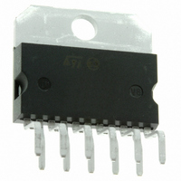
Package / Case
Multiwatt-11 (Vertical, Bent and Staggered Leads)
Operational Class
Class-AB
Output Power (typ)
22W
Audio Amplifier Function
Speaker
Total Harmonic Distortion
0.05%%
Single Supply Voltage (typ)
9/12/15V
Dual Supply Voltage (typ)
Not RequiredV
Power Supply Requirement
Single
Power Dissipation
36W
Rail/rail I/o Type
No
Power Supply Rejection Ratio
62dB
Single Supply Voltage (min)
8V
Single Supply Voltage (max)
18V
Dual Supply Voltage (min)
Not RequiredV
Dual Supply Voltage (max)
Not RequiredV
Operating Temp Range
-40C to 150C
Operating Temperature Classification
Automotive
Mounting
Through Hole
Pin Count
11 +Tab
Package Type
MULTIWATT V
Lead Free Status / RoHS Status
Lead free / RoHS Compliant
Other names
497-3973-5
Available stocks
Company
Part Number
Manufacturer
Quantity
Price

Part Number:
TDA7360
Manufacturer:
ST
Quantity:
20 000


TDA7360
List of figures
Figure 1.
Figure 2.
Figure 3.
Figure 4.
Figure 5.
Figure 6.
Figure 7.
Figure 8.
Figure 9.
Figure 10.
Figure 11.
Figure 12.
Figure 13.
Figure 14.
Figure 15.
Figure 16.
Figure 17.
Figure 18.
Figure 19.
Figure 20.
Figure 21.
Figure 22.
Figure 23.
Figure 24.
Figure 25.
Figure 26.
Figure 27.
Figure 28.
Figure 29.
Figure 30.
Figure 31.
Figure 32.
Figure 33.
Figure 34.
Figure 35.
Figure 36.
Figure 37.
Figure 38.
Figure 39.
Figure 40.
Figure 41.
Figure 42.
Figure 43.
Figure 44.
Figure 45.
Figure 46.
Figure 47.
Figure 48.
Figure 49.
Block diagram (stereo configuration) . . . . . . . . . . . . . . . . . . . . . . . . . . . . . . . . . . . . . . . . . . 6
Block diagram (bridge configuration) . . . . . . . . . . . . . . . . . . . . . . . . . . . . . . . . . . . . . . . . . . 6
Pins connection (top view) . . . . . . . . . . . . . . . . . . . . . . . . . . . . . . . . . . . . . . . . . . . . . . . . . . 7
Stereo test and application circuit . . . . . . . . . . . . . . . . . . . . . . . . . . . . . . . . . . . . . . . . . . . . 10
Printed circuit board of the stereo application circuit . . . . . . . . . . . . . . . . . . . . . . . . . . . . . 10
Bridge test and application circuit . . . . . . . . . . . . . . . . . . . . . . . . . . . . . . . . . . . . . . . . . . . . 11
Printed circuit board of the bridge application circuit . . . . . . . . . . . . . . . . . . . . . . . . . . . . . 11
Output power vs. supply voltage (Stereo, 4 Ω) . . . . . . . . . . . . . . . . . . . . . . . . . . . . . . . . . . 12
Output power vs. supply voltage (Stereo, 2 Ω) . . . . . . . . . . . . . . . . . . . . . . . . . . . . . . . . . . 12
Output power vs. supply voltage (Stereo, 3.2 Ω) . . . . . . . . . . . . . . . . . . . . . . . . . . . . . . . . 12
Output power vs. supply voltage (Bridge, 4 Ω) . . . . . . . . . . . . . . . . . . . . . . . . . . . . . . . . . . 12
Output power vs. supply voltage (Bridge, 3.2 Ω) . . . . . . . . . . . . . . . . . . . . . . . . . . . . . . . . 12
Drain current vs. supply voltage (Stereo) . . . . . . . . . . . . . . . . . . . . . . . . . . . . . . . . . . . . . . 12
Distortion vs. output power (Stereo, 4 Ω) . . . . . . . . . . . . . . . . . . . . . . . . . . . . . . . . . . . . . . 13
Distortion vs. output power (Stereo, 3.2 Ω). . . . . . . . . . . . . . . . . . . . . . . . . . . . . . . . . . . . . 13
Distortion vs. output power (Stereo, 2 Ω) . . . . . . . . . . . . . . . . . . . . . . . . . . . . . . . . . . . . . . 13
Distortion vs. output power (Bridge, 4 Ω) . . . . . . . . . . . . . . . . . . . . . . . . . . . . . . . . . . . . . . 13
Distortion vs. output power (Bridge, 3.2 Ω). . . . . . . . . . . . . . . . . . . . . . . . . . . . . . . . . . . . . 13
SVR vs. frequency and C3 (Stereo) . . . . . . . . . . . . . . . . . . . . . . . . . . . . . . . . . . . . . . . . . . 13
SVR vs. frequency and C3 (Bridge) . . . . . . . . . . . . . . . . . . . . . . . . . . . . . . . . . . . . . . . . . . 14
Crosstalk vs. frequency (Stereo) . . . . . . . . . . . . . . . . . . . . . . . . . . . . . . . . . . . . . . . . . . . . 14
Power dissipation and efficiency vs. output power (Stereo, 2 Ω) . . . . . . . . . . . . . . . . . . . . 14
Power dissipation and efficiency vs. output power (Stereo, 4 Ω) . . . . . . . . . . . . . . . . . . . . 14
Power dissipation and efficiency vs. output power (Bridge, 4 Ω) . . . . . . . . . . . . . . . . . . . . 14
Power dissipation and efficiency vs. output power (Bridge, 3.2 Ω). . . . . . . . . . . . . . . . . . . 14
Turn-on delay circuit . . . . . . . . . . . . . . . . . . . . . . . . . . . . . . . . . . . . . . . . . . . . . . . . . . . . . . 16
Mute function diagram . . . . . . . . . . . . . . . . . . . . . . . . . . . . . . . . . . . . . . . . . . . . . . . . . . . . 17
Dual channel distortion detector . . . . . . . . . . . . . . . . . . . . . . . . . . . . . . . . . . . . . . . . . . . . . 17
Output at clipping detector pin vs. signal distortion . . . . . . . . . . . . . . . . . . . . . . . . . . . . . . 17
ICV - PNP gain vs. IC . . . . . . . . . . . . . . . . . . . . . . . . . . . . . . . . . . . . . . . . . . . . . . . . . . . . . 18
ICV - PNP VCE(sat) vs. IC . . . . . . . . . . . . . . . . . . . . . . . . . . . . . . . . . . . . . . . . . . . . . . . . . 18
ICV - PNP cut-off frequency vs. IC . . . . . . . . . . . . . . . . . . . . . . . . . . . . . . . . . . . . . . . . . . . 18
The new output stage . . . . . . . . . . . . . . . . . . . . . . . . . . . . . . . . . . . . . . . . . . . . . . . . . . . . . 19
A classical output stage . . . . . . . . . . . . . . . . . . . . . . . . . . . . . . . . . . . . . . . . . . . . . . . . . . . 19
Amplifier block diagram . . . . . . . . . . . . . . . . . . . . . . . . . . . . . . . . . . . . . . . . . . . . . . . . . . . 19
Circuitry for short circuit detection . . . . . . . . . . . . . . . . . . . . . . . . . . . . . . . . . . . . . . . . . . . 20
Suggested LC network circuit . . . . . . . . . . . . . . . . . . . . . . . . . . . . . . . . . . . . . . . . . . . . . . . 21
Voltage gain bridge configuration . . . . . . . . . . . . . . . . . . . . . . . . . . . . . . . . . . . . . . . . . . . . 21
Maximum allowable power dissipation vs. ambient temperature . . . . . . . . . . . . . . . . . . . . 22
Restart circuit . . . . . . . . . . . . . . . . . . . . . . . . . . . . . . . . . . . . . . . . . . . . . . . . . . . . . . . . . . . 22
Output waveforms compared to the values of Csvr . . . . . . . . . . . . . . . . . . . . . . . . . . . . . . 24
ST-BY pin supply circuit, example 1 . . . . . . . . . . . . . . . . . . . . . . . . . . . . . . . . . . . . . . . . . . 25
ST-BY pin supply circuit, example 2 . . . . . . . . . . . . . . . . . . . . . . . . . . . . . . . . . . . . . . . . . . 25
Suggested muting circuit during amplifier switch-on and switch-off . . . . . . . . . . . . . . . . . . 26
Timing diagram for the circuit depicted in fig. 44 . . . . . . . . . . . . . . . . . . . . . . . . . . . . . . . . 26
Modification of the circuit depicted in fig.44 to drive two amplifiers . . . . . . . . . . . . . . . . . . 26
Balance input bridge configuration, example 1 . . . . . . . . . . . . . . . . . . . . . . . . . . . . . . . . . . 27
Balance input bridge configuration, example 2 . . . . . . . . . . . . . . . . . . . . . . . . . . . . . . . . . . 27
Multiwatt11 (vertical) mechanical data and package dimensions . . . . . . . . . . . . . . . . . . . . 28
Doc ID 1499 Rev 3
List of figures
5/30
Related parts for TDA7360
Image
Part Number
Description
Manufacturer
Datasheet
Request
R

Part Number:
Description:
STMicroelectronics [RIPPLE-CARRY BINARY COUNTER/DIVIDERS]
Manufacturer:
STMicroelectronics
Datasheet:
Part Number:
Description:
STMicroelectronics [LIQUID-CRYSTAL DISPLAY DRIVERS]
Manufacturer:
STMicroelectronics
Datasheet:

Part Number:
Description:
BOARD EVAL FOR MEMS SENSORS
Manufacturer:
STMicroelectronics
Datasheet:
Part Number:
Description:
NPN TRANSISTOR POWER MODULE
Manufacturer:
STMicroelectronics
Datasheet:
Part Number:
Description:
TURBOSWITCH ULTRA-FAST HIGH VOLTAGE DIODE
Manufacturer:
STMicroelectronics
Datasheet:
Part Number:
Description:
Manufacturer:
STMicroelectronics
Datasheet:
Part Number:
Description:
DIODE / SCR MODULE
Manufacturer:
STMicroelectronics
Datasheet:
Part Number:
Description:
DIODE / SCR MODULE
Manufacturer:
STMicroelectronics
Datasheet:
Part Number:
Description:
Search -----> STE16N100
Manufacturer:
STMicroelectronics
Datasheet:
Part Number:
Description:
Search ---> STE53NA50
Manufacturer:
STMicroelectronics
Datasheet:
Part Number:
Description:
NPN Transistor Power Module
Manufacturer:
STMicroelectronics
Datasheet:
Part Number:
Description:
DIODE / SCR MODULE
Manufacturer:
STMicroelectronics
Datasheet: