ISD5108EYI Nuvoton Technology Corporation of America, ISD5108EYI Datasheet - Page 11
ISD5108EYI
Manufacturer Part Number
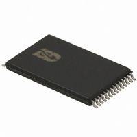
ISD5108EYI
Description
IC VOICE REC/PLAY 4-8MN 28-TSOP
Manufacturer
Nuvoton Technology Corporation of America
Series
ISD5100r
Datasheet
1.ISD5116SY.pdf
(90 pages)
Specifications of ISD5108EYI
Interface
I²C
Filter Pass Band
1.7 ~ 3.4kHz
Duration
4 ~ 8 Min
Mounting Type
Surface Mount
Package / Case
28-TSOP
For Use With
ISD-ES511 - EVALUATION SYSTEM FOR ISD5100ISD-ES501 - EVALUATION SYSTEM FOR ISD5008
Lead Free Status / RoHS Status
Lead free / RoHS Compliant


operation, voice from Mic inputs are fed to AUX OUT and transmitted to the phone line, while
message from other party is input from the AUX IN, then fed through to the speaker for listening.
The ISD5100 device has the flexibility for other applications, because the audio paths can be
configured differently, with each circuit block being powered-up or –down individually, according to the
applications requirement.
The ISD5100 Series have multiple internal registers that are used to store the address information and
the configuration or set-up of the device. The two 16-bit configuration registers control the audio paths
through the device, the sample frequency, the various gains and attenuations, power up and down of
different sections, and the volume settings. These registers are discussed in detail in
The ISD5100 Series memory array are arranged in various pages (or rows) of each 2048 bits as
follows. The primary addressing for the pages are handled by 11 bits of address input in the analog
mode.
A memory page is 2048 bits organized as thirty-two 64-bit "blocks" when used for digital storage. The
contents of a page are either analog or digital. This is determined by instruction (opcode) at the time
the data is written. A record of where is analog and where is digital, is stored in a message address
table (MAT) by the system microcontroller. The MAT is a table kept in the microcontroller memory that
defines the status of each message “page”. It can be stored back into the ISD5100 Series if the power
fails or the system is turned off. Using this table allows efficient message management. Segments of
messages can be stored wherever there is available space in the memory array. [This is explained in
detail for the ISD5008 in Applications Note #9 and will be similarly described in a later Note for the
ISD5100-Series.]
When a page is used for analog storage, the same 32 blocks are present but there are 8 EOM (End-
of-Message) markers. This means that for each 4 blocks there is an EOM marker at the end. Thus,
when recording, the analog recording will stop at any one of eight positions. At 8 kHz sampling
frequency, this results in a resolution of 32 msec when ENDING an analog recording. Beginning an
analog recording is limited to the 256 msec resolution provided by the 11-bit address. A recording
does not immediately stop when the Stop command is given, but continues until the 32 millisecond
block is filled. Then a bit is placed in the EOM memory to develop the interrupt that signals a
message is finished playing in the Playback mode.
6.2.1
6.2.2
Internal Registers
Memory Architecture
Products
ISD5116
ISD5108
ISD5104
ISD5102
Pages (Rows)
2048
1024
512
256
- 11 -
Bits/Page
2048
2048
2048
2048
Publication Release Date: Oct 31, 2008
4,194,304 bits
2,097,152 bits
1,048,576 bits
Memory Size
524,288 bits
ISD5100 SERIES
section
Revision 1.42
7.3.5.
Related parts for ISD5108EYI
Image
Part Number
Description
Manufacturer
Datasheet
Request
R

Part Number:
Description:
Manufacturer:
Nuvoton Technology Corporation of America
Datasheet:
Part Number:
Description:
Manufacturer:
Nuvoton Technology Corporation of America
Datasheet:
Part Number:
Description:
Manufacturer:
Nuvoton Technology Corporation of America
Datasheet:
Part Number:
Description:
Manufacturer:
Nuvoton Technology Corporation of America
Datasheet:
Part Number:
Description:
Manufacturer:
Nuvoton Technology Corporation of America
Datasheet:
Part Number:
Description:
Manufacturer:
Nuvoton Technology Corporation of America
Datasheet:
Part Number:
Description:
Manufacturer:
Nuvoton Technology Corporation of America
Datasheet: