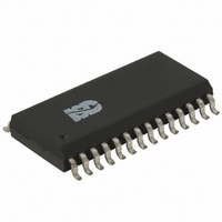
ISD5108SY Nuvoton Technology Corporation of America, ISD5108SY Datasheet - Page 37

ISD5108SY
Manufacturer Part Number
ISD5108SY
Description
IC VOICE REC/PLAY 4-8MN 28-SOIC
Manufacturer
Nuvoton Technology Corporation of America
Series
ISD5100r
Datasheet
1.ISD5116SY.pdf
(90 pages)
Specifications of ISD5108SY
Interface
I²C
Filter Pass Band
1.7 ~ 3.4kHz
Duration
4 ~ 8 Min
Mounting Type
Surface Mount
Package / Case
28-SOIC (0.300", 7.50mm Width)
Lead Free Status / RoHS Status
Lead free / RoHS Compliant
For Use With
ISD-ES511 - EVALUATION SYSTEM FOR ISD5100ISD-ES501 - EVALUATION SYSTEM FOR ISD5008
Lead Free Status / RoHS Status
Supplier Unconfirmed, Lead free / RoHS Compliant
- Current page: 37 of 90
- Download datasheet (674Kb)
The Digital Read command utilizes the combined I
the chip using the write data direction. Then the data direction is reversed by sending a repeated
start condition, and the slave address with R/W set to 1. After this, the slave device (ISD5100-
Series) begins to send data to the master until the master generates a NACK. If the part encounters
an overflow condition, the
possible due to the master generating ACK signals.
Digital Write and Digital Read can be done a “block” at a time. Thus, only 64 bits need be read in
each Digital Read command sequence.
An explanation and graphical representation of the Erase, Write and Read operations are found
below.
Note: All sequences assumes that the chip is in power-down mode before the commands are sent.
Erase
=====
I2CStart
SendByte(0x80)
WaitACK
WaitSCLHigh
SendByte(0xc0)
WaitACK
WaitSCLHigh
I2CStop
I2CStart
SendByte(0x80)
WaitACK
WaitSCLHigh
SendByte(0xd1)
WaitACK
WaitSCLHigh
6.5.3
6.5.4
6.5.4.1. Erase Digital Data
Reading Digital Data
Example Command Sequences
- Enter Digital Mode Command
- Write, Slave address zero
- Write, Slave address zero
- Digital Erase Command
INT
pin is pulled LOW. No other communication with the master is
- 37 -
2
C command format. That is, a command is sent to
Publication Release Date: Oct 31, 2008
ISD5100 SERIES
Revision 1.42
Related parts for ISD5108SY
Image
Part Number
Description
Manufacturer
Datasheet
Request
R

Part Number:
Description:
MODULE FOR VOICE REC/PLAY 10S
Manufacturer:
Nuvoton Technology Corporation of America

Part Number:
Description:
Manufacturer:
Nuvoton Technology Corporation of America
Datasheet:

Part Number:
Description:
Manufacturer:
Nuvoton Technology Corporation of America
Datasheet:

Part Number:
Description:
Manufacturer:
Nuvoton Technology Corporation of America
Datasheet:

Part Number:
Description:
Manufacturer:
Nuvoton Technology Corporation of America
Datasheet:

Part Number:
Description:
Manufacturer:
Nuvoton Technology Corporation of America
Datasheet:

Part Number:
Description:
Manufacturer:
Nuvoton Technology Corporation of America
Datasheet:


