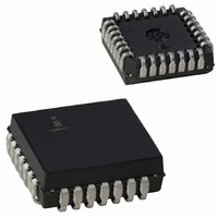
IS82C52Z Intersil, IS82C52Z Datasheet - Page 9

IS82C52Z
Manufacturer Part Number
IS82C52Z
Description
IC CONTROLLER UART 28-PLCC
Manufacturer
Intersil
Datasheet
1.IS82C52Z.pdf
(20 pages)
Specifications of IS82C52Z
Features
Single Chip UART/BRG
Number Of Channels
1, UART
Protocol
RS232C
Voltage - Supply
4.5 V ~ 5.5 V
With Parallel Port
Yes
With False Start Bit Detection
Yes
With Modem Control
Yes
With Cmos
Yes
Mounting Type
Surface Mount
Package / Case
28-LCC (J-Lead)
Peak Reflow Compatible (260 C)
Yes
Rohs Compliant
Yes
Lead Free Status / RoHS Status
Lead free / RoHS Compliant
Available stocks
Company
Part Number
Manufacturer
Quantity
Price
transmission. The transmitter always has the same word
length and number of stop bits as the receiver. For words of
less than 8 bits the unused bits at the microprocessor data
bus are ignored by the transmitter.
Bit 0, which corresponds to D0 at the data bus, is always the
first serial data bit transmitted. Provision is made for the
transmitter parity to be the same or different from the
receiver. The TBRE output pin and flag (USR register) reflect
the status of the TBR. The TC flag (USR register) indicates
when both TBR and TR are empty.
82C52 Interrupt Structure
The 82C52 has provisions for software masking of interrupts
generated for the INTR output pin. Two control bits in the
MCR register, MIEN and INTEN, control modem status
interrupts and overall 82C52 interrupts respectively. Figure 9
illustrates the logical control function provided by these
signals.
The modem status inputs (DSR and CTS) will trigger the
edge detection circuitry with any change of status. Reading
the MSR register will clear the detect circuit but has no effect
on the status bits themselves. These status bits always
reflect the state of the input pins regardless of the mask
control signals. Note that the state (high or low) of the status
bits are inverted versions of the actual input pins.
The edge detection circuits for the USR register signals will
trigger only for a positive edge (true assertion) of these
status bits. Reading the USR register not only clears the
edge detect circuit but also clears (sets to 0) all of the status
bits. The output pins associated with these status bits are not
affected by reading the USR register.
A hardware reset of the 82C52 sets the TC status bit in the
USR. When interrupts are subsequently enabled an interrupt
can occur due to the fact that the positive edge detection
circuitry in the interrupt logic has detected the setting of the
TC bit. If this interrupt is not desired the USR should be read
prior to enabling interrupts. This action resets the positive
edge detection circuitry in the interrupt control logic (Figure 9).
NOTE: For USR and MSR, the setting of status bits is inhibited
during status register READ operations. If a status condition is
D7 D6 D5 D4 D3 D2 D1 D0
FIGURE 8. TBR
9
Bit 0
Bit 1
Bit 2
Bit 3
Bit 4
Bit 5
Bit 6
Bit 7
5-Bit
Word
6-Bit
Word
7-Bit
Word
8-Bit
Word
82C52
82C52
generated during a READ operation, the status bit is not set until the
trailing edge of the RD pulse.
If the bit was already set at the time of the READ operation, and the
same status condition occurs, that status bit will be cleared at the
trailing edge of the RD pulse instead of being set again.
Software Reset
A software reset of the 82C52 is a useful method for
returning to a completely known state without exercising a
complete system reset. Such a reset would consist of writing
to the UCR, BRSR and MCR registers. The USR and RBR
registers should be read prior to enabling interrupts in order
to clear out any residual data or status bits which may be
invalid for subsequent operation.
Crystal Operation
The 82C52 crystal oscillator circuitry is designed to operate
with a fundamental mode, parallel resonant crystal. This
circuit is the same one used in the Intersil 82C84A clock
generator/driver. To summarize, Table 3 and Figure 10 show
the required crystal parameters and crystal circuit
configuration respectively.
When using an external clock source, the IX input is driven
and the OX output is left open. Power consumption when
using an external clock is typically 50% of that required when
using a crystal. This is due to the sinusoidal nature of the
drive circuitry when using a crystal.
Frequency
Type of Operation
Load Capacitance (CL)
R
OE, FE, PE
RBRK, TC
DSR, CTS
RD (MSR)
SERIES
RD (USR)
(MSR)
(USR)
PARAMETER
(Max)
FIGURE 9. 82C52 INTERRUPT STRUCTURE
POS. OR
DETECT
DETECT
EDGE
EDGE
POS.
NEG.
20 or 32pF (Typ)
100Ω (f = 16MHz, CL = 32pF)
200Ω (f = 16MHz, CL = 20pF)
1.0 to 16MHz
Parallel Resonant, Fundamental Mode
TABLE 3.
(MCR)
MIEN
TYPICAL CRYSTAL
SPECIFICATION
INTEN
(MCR)
April 26, 2006
PIN 24
FN2950.3
INTR


