SCC2692AC1N40,602 NXP Semiconductors, SCC2692AC1N40,602 Datasheet - Page 17
SCC2692AC1N40,602
Manufacturer Part Number
SCC2692AC1N40,602
Description
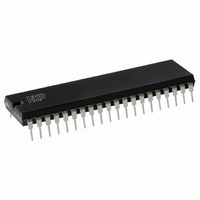
IC UART DUAL 40-DIP
Manufacturer
NXP Semiconductors
Type
Dual UARTr
Datasheet
1.SCC2692AC1N40602.pdf
(30 pages)
Specifications of SCC2692AC1N40,602
Number Of Channels
2, DUART
Package / Case
40-DIP (0.600", 15.24mm)
Features
False-start Bit Detection
Fifo's
3Bit
Voltage - Supply
5V
With Parallel Port
Yes
With Auto Flow Control
Yes
With False Start Bit Detection
Yes
With Cmos
Yes
Mounting Type
Through Hole
Data Rate
0.1152 MBd
Supply Voltage (max)
5.5 V
Supply Voltage (min)
4.5 V
Supply Current
10 mA
Maximum Operating Temperature
+ 70 C
Minimum Operating Temperature
0 C
Mounting Style
SMD/SMT
Operating Supply Voltage
5 V
Lead Free Status / RoHS Status
Lead free / RoHS Compliant
Lead Free Status / RoHS Status
Lead free / RoHS Compliant, Lead free / RoHS Compliant
Other names
568-1216-5
933977590602
SCC2692AC1N40
933977590602
SCC2692AC1N40
Available stocks
Company
Part Number
Manufacturer
Quantity
Price
Company:

Part Number:
SCC2692AC1N40,602
Manufacturer:
Exar
Quantity:
46


Philips Semiconductors
OPCR – Output Port Configuration Register
OPCR[7] – OP7 Output Select
This bit programs the OP7 output to provide one of the following:
0 The complement of OPR[7].
1 The Channel B transmitter interrupt output which is the
OPCR[6] – OP6 Output Select
This bit programs the OP6 output to provide one of the following:
0 The complement of OPR[6].
1 The Channel A transmitter interrupt output which is the
OPCR[5] – OP5 Output Select
This bit programs the OP5 output to provide one of the following:
0 The complement of OPR[5].
1 The Channel B transmitter interrupt output which is the
OPCR[4] – OP4 Output Select
This field programs the OP4 output to provide one of the following:
0 The complement of OPR[4].
1 The Channel A receiver interrupt output which is the complement
OPCR[3:2] – OP3 Output Select
This bit programs the OP3 output to provide one of the following:
00 The complement of OPR[3].
01 The counter/timer output, in which case OP3 acts as an
10 The 1X clock for the Channel B transmitter, which is the clock
11 The 1X clock for the Channel B receiver, which is the clock that
OPCR[1:0] – OP2 Output Select
This field programs the OP2 output to provide one of the following:
00 The complement of OPR[2].
01 The 16X clock for the Channel A transmitter. This is the clock
1998 Sep 04
Dual asynchronous receiver/transmitter (DUART)
complement of TxRDYB. When in this mode OP7 acts as an
open- drain output. Note that this output is not masked by the
contents of the IMR.
complement of TxRDYA. When in this mode OP6 acts as an
open- drain output. Note that this output is not masked by the
contents of the IMR.
complement of ISR[5]. When in this mode OP5 acts as an
open-drain output. Note that this output is not masked by the
contents of the IMR.
of ISR[1]. When in this mode OP4 acts as an open-drain output.
Note that this output is not masked by the contents of the IMR.
open-drain output. In the timer mode, this output is a square
wave at the programmed frequency. In the counter mode, the
output remains High until terminal count is reached, at which
time it goes Low. The output returns to the High state when the
counter is stopped by a stop counter command. Note that this
output is not masked by the contents of the IMR.
that shifts the transmitted data. If data is not being transmitted, a
free running 1X clock is output.
samples the received data. If data is not being received, a free
running 1X clock is output.
selected by CSRA[3:0], and will be a 1X clock if CSRA[3:0] =
1111.
17
10 The 1X clock for the Channel A transmitter, which is the clock
11 The 1X clock for the Channel A receiver, which is the clock that
ACR – Auxiliary Control Register
ACR[7] – Baud Rate Generator Set Select
This bit selects one of two sets of baud rates to be generated by the
BRG:
Set 1:
Set 2:
Table 4. Bit Rate Generator Characteristics
Crystal or Clock = 3.6864MHz
The selected set of rates is available for use by the Channel A and
B receivers and transmitters as described in CSRA and CSRB.
Baud rate generator characteristics are given in Table 4.
ACR[6:4] – Counter/Timer Mode And Clock Source Select
This field selects the operating mode of the counter/timer and its
clock source as shown in Table 5.
ACR[3:0] – IP3, IP2, IP1, IP0 Change-of-State Interrupt Enable
This field selects which bits of the input port change register (IPCR)
cause the input change bit in the interrupt status register (ISR[7]) to
be set. If a bit is in the ‘on’ state the setting of the corresponding bit
in the IPCR will also result in the setting of ISR[7], which results in
the generation of an interrupt output if IMR[7] = 1. If a bit is in the
‘off’ state, the setting of that bit in the IPCR has no effect on ISR[7].
NOTE: Duty cycle of 16X clock is 50% 1%.
BAUD RATE
that shifts the transmitted data. If data is not being transmitted, a
free running 1X clock is output.
samples the received data. If data is not being received, a free
running 1X clock is output.
115.2K
14.4K
19.2K
28.8K
38.4K
57.6K
134.5
1050
1200
1800
2000
2400
4800
7200
9600
150
200
300
600
110
50
75
50, 110, 134.5, 200, 300, 600, 1.05K, 1.2K, 2.4K, 4.8K,
7.2K, 9.6K, and 38.4K baud.
75, 110, 134.5, 150, 300, 600, 1.2K, 1.8K, 2.0K, 2.4K,
4.8K, 9.6K, and 19.2K baud.
ACTUAL 16X CLOCK (kHz)
1,843.2
16.756
32.056
1.759
2.153
153.6
230.4
307.2
460.8
614.4
921.2
115.2
19.2
28.8
38.4
76.8
0.8
1.2
2.4
3.2
4.8
9.6
Product specification
SCC2692
ERROR (%)
-0.069
-0.260
0.059
0.175
0
0
0
0
0
0
0
0
0
0
0
0
0
0
0
0
0
0
Related parts for SCC2692AC1N40,602
Image
Part Number
Description
Manufacturer
Datasheet
Request
R

Part Number:
Description:
Dual asynchronous receiver/transmitter DUART
Manufacturer:
Philips
Datasheet:

Part Number:
Description:
NXP Semiconductors designed the LPC2420/2460 microcontroller around a 16-bit/32-bitARM7TDMI-S CPU core with real-time debug interfaces that include both JTAG andembedded trace
Manufacturer:
NXP Semiconductors
Datasheet:

Part Number:
Description:
NXP Semiconductors designed the LPC2458 microcontroller around a 16-bit/32-bitARM7TDMI-S CPU core with real-time debug interfaces that include both JTAG andembedded trace
Manufacturer:
NXP Semiconductors
Datasheet:
Part Number:
Description:
NXP Semiconductors designed the LPC2468 microcontroller around a 16-bit/32-bitARM7TDMI-S CPU core with real-time debug interfaces that include both JTAG andembedded trace
Manufacturer:
NXP Semiconductors
Datasheet:
Part Number:
Description:
NXP Semiconductors designed the LPC2470 microcontroller, powered by theARM7TDMI-S core, to be a highly integrated microcontroller for a wide range ofapplications that require advanced communications and high quality graphic displays
Manufacturer:
NXP Semiconductors
Datasheet:
Part Number:
Description:
NXP Semiconductors designed the LPC2478 microcontroller, powered by theARM7TDMI-S core, to be a highly integrated microcontroller for a wide range ofapplications that require advanced communications and high quality graphic displays
Manufacturer:
NXP Semiconductors
Datasheet:
Part Number:
Description:
The Philips Semiconductors XA (eXtended Architecture) family of 16-bit single-chip microcontrollers is powerful enough to easily handle the requirements of high performance embedded applications, yet inexpensive enough to compete in the market for hi
Manufacturer:
NXP Semiconductors
Datasheet:
Part Number:
Description:
The XA-S3 device is a member of Philips Semiconductors? XA(eXtended Architecture) family of high performance 16-bitsingle-chip microcontrollers
Manufacturer:
NXP Semiconductors
Datasheet:

Part Number:
Description:
The NXP BlueStreak LH75401/LH75411 family consists of two low-cost 16/32-bit System-on-Chip (SoC) devices
Manufacturer:
NXP Semiconductors
Datasheet:
Part Number:
Description:
The NXP LPC3130/3131 combine an 180 MHz ARM926EJ-S CPU core, high-speed USB2
Manufacturer:
NXP Semiconductors
Datasheet:
Part Number:
Description:
The NXP LPC3141 combine a 270 MHz ARM926EJ-S CPU core, High-speed USB 2
Manufacturer:
NXP Semiconductors
Part Number:
Description:
The NXP LPC3143 combine a 270 MHz ARM926EJ-S CPU core, High-speed USB 2
Manufacturer:
NXP Semiconductors

Part Number:
Description:
The NXP LPC3152 combines an 180 MHz ARM926EJ-S CPU core, High-speed USB 2
Manufacturer:
NXP Semiconductors
Part Number:
Description:
The NXP LPC3154 combines an 180 MHz ARM926EJ-S CPU core, High-speed USB 2
Manufacturer:
NXP Semiconductors