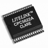
CPC5622ATR Clare, CPC5622ATR Datasheet - Page 10

CPC5622ATR
Manufacturer Part Number
CPC5622ATR
Description
LITELINK III PHONE LINE 32SOIC
Manufacturer
Clare
Series
LITELINK® IIIr
Specifications of CPC5622ATR
Function
Data Access Arrangement (DAA)
Number Of Circuits
1
Voltage - Supply
3 V ~ 5.5 V
Current - Supply
9mA
Power (watts)
1W
Operating Temperature
-40°C ~ 85°C
Mounting Type
Surface Mount
Package / Case
32-SOIC (7.5mm Width)
Includes
CID Monitoring, Full-Wave Ring Detector, Half-Wave Ring Detector
Operating Temperature (min)
-40C
Operating Temperature Classification
Industrial
Operating Temperature (max)
85C
Package Type
SOIC
Rad Hardened
No
Lead Free Status / RoHS Status
Lead free / RoHS Compliant
Interface
-
Lead Free Status / Rohs Status
Compliant
Other names
CLA322TR
CPC5622ATR
CPC5622ATR
Available stocks
Company
Part Number
Manufacturer
Quantity
Price
Company:
Part Number:
CPC5622ATR
Manufacturer:
Maxim
Quantity:
2 078
CPC5622
3. Using LITELINK
As a full-featured telephone line interface, LITELINK
performs the following functions:
•
•
•
•
•
•
•
LITELINK can accommodate specific application
features without sacrificing basic functionality or
performance. Application features include, but are not
limited to:
•
•
•
•
•
•
•
•
This section of the data sheet describes LITELINK
operation in standard configuration for usual
operation. Clare offers additional application
information on-line
following topics:
•
•
•
•
•
•
Other specific application materials are also
referenced in this section as appropriate.
3.1 Switch Hook Control (On-hook
and Off-hook States)
LITELINK operates in one of two conditions, on-hook
and off-hook. In the on-hook condition the telephone
line is available for calls. In the off-hook condition the
telephone line is engaged. The OH control input is
used to place LITELINK in one of these two states.
With OH high, LITELINK is on-hook and ready to
make or receive a call. Also while on-hook,
10
DC termination and V/I slope control
AC impedance control
2-wire to 4-wire conversion (hybrid)
Current limiting
Ringing detect signalling reception
Caller ID signalling reception
Switch hook
High transmit power operation
Pulse dialing
Ground start
Loop start
Parallel telephone off-hook detection (line intrusion)
Battery reversal detection
Line presence detection
World-wide programmable operation
Circuit isolation considerations
Optimizing LITELINK performance
Data Access Arrangement architecture
LITELINK circuit descriptions
Surge protection
EMI considerations
(see Section 5 on page 14)
for the
www.clare.com
LITELINK’s ringing detector and CID amplifiers are
both active.
Asserting OH low causes LITELINK to answer or
originate a call by entering the off-hook state. In the
off-hook state, loop current flows through LITELINK.
3.2 On-hook Operation: OH=1
The LITELINK application circuit leakage current is
less than 10 μA with 100 V across ring and tip,
equivalent to greater than 10 MΩ on-hook resistance.
3.2.1 Ringing Signal Reception via the
In the on-hook state (OH not asserted), an internal
multiplexer engages the snoop circuitry. This circuit
simultaneously monitors the telephone line for two
conditions; incoming ringing signal and caller ID data
bursts.
Refer to the application schematic diagram
3 on page
high-voltage isolation barrier between the telephone
line and SNP- and SNP+ input pins of the LITELINK
while coupling AC signals to the snoop amplifier. The
snoop circuit “snoops” the telephone line continuously
while drawing no dc current. In the LITELINK, the
incoming ringing signals are compared to a reference
level. When the ringing signal exceeds the preset
threshold, the internal comparators generate the
RING and RING2 signals which are output from
LITELINK at pins 9 and 10, respectively. Selection of
which output to use is dependent upon the support
logic responsible for monitoring and filtering the
ringing detect signals. To reduce or eliminate false
ringing detects this signal should be digitally filtered
and qualified by the system as a valid ringing signal. A
logic low output on RING or RING2 indicates that the
LITELINK ringing signal detect threshold has been
exceeded. In the absence of any incoming ac signal
the RING and RING2 outputs are held high.
The CPC5622 RING output signal is generated by a
half-wave ringing detector while the RING2 output is
generated by a full-wave ringing detector. A half-wave
ringing detector’s output frequency follows the
frequency of the incoming ringing signal from the
Central Office (CO) while a full-wave ringing detector’s
output frequency is twice that of the incoming signal.
Because RING is the output of a half-wave detector, it
will output one logic low pulse per cycle of the ringing
frequency. Also, because the RING2 is the output of a
Snoop Circuit
6). C7 (C
SNP-
) and C8 (C
SNP+
) provide a
(see Figure
R02


