2469-63-54-0-AFB-1-M YOKOGAWA, 2469-63-54-0-AFB-1-M Datasheet - Page 10
2469-63-54-0-AFB-1-M
Manufacturer Part Number
2469-63-54-0-AFB-1-M
Description
63K2357
Manufacturer
YOKOGAWA
Datasheet
1.2489-63-54-0-AHF-1-0-M.pdf
(32 pages)
Specifications of 2469-63-54-0-AFB-1-M
Transducer Function
VAR 3P3W (2 Element)
Supply Voltage Min
100V
Supply Voltage Max
135V
Transducer Input Current Ac
5A
Frequency
60Hz
Supply Voltage
120VAC
Rohs Compliant
NA


1) GENERAL
2) SPECIFICATIONS
3) STANDARD MODELS
NOTE: See order format on next page for additional ratings, frequency calibrations, power-up and output options.
Model #
Current input / range
Current input over range capability
Current input burden
Voltage inputs and range:
Voltage input burden per element
Sustained Voltage input overange
Rated outputs
Accuracy
Output calibration / element
External calibration adjustment
Response time
Output ripple
Isolation
Surge Withstand Capability
Insulation resistance
Operating temperature
Operating humidity
Temperature effect
External magnetic field
Influence : unbalanced currents /
phase interaction / Power Factor
Influence of frequency
Weight
Shock
Vibration
UL Recognition
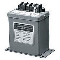
120 VAC, 5AAC, 60 Hz, input powered
The 2469 and 2489 AC Watt transducers produce an analog output equal to the Watts measured by the
input. The typical calibration is 500 Watts / element for 120V and 5A AC transformer secondary inputs.
Watt 1P2W, 0-1mA output (1 Element)
Watt 1P2W, 4-20mA output (1 Element)
Watt 3P3W, 0-1mA output (2 Element)
Watt 3P3W, 4-20mA output (2 Element)
Watt 3P4W, 0-1mA output (2
Watt 3P4W, 4-20mA output (2
Watt 3P4W, 0-1mA output (3 Element)
Watt 3P4W, 4-20mA output (3 Element)
Auxiliary power supply options <5.0 VA burden.
Input powered range
Auxiliary powered range
1
⁄
J U X T A
2
1
⁄
Element)
2
Element)
A C
150% of rated input without damage (Auxiliary powered only)
0.3% of span peak-to-peak max. 0.5% of span peak-to-peak max.
0 to ±1mADC into 10kΩ max. load; 10VDC output compliance
100-135VAC
IEEE472/ANSI C37.90.1 - 1989, JIS C1111 (5KV 1.2 x 50 microseconds)
0 ± 1mADC = 0.5% of full scale
4-20 mADC into 750Ω max. load; 15VDC output compliance
W A T T
10 to 200% of rated input
4-20mADC = 0.5% of span
< 0.5VA
120V
Span: ± 2% minimum
<0.25%, 45-65 Hz, fundamental through 9th harmonic
2469 (0.5% Accuracy)
Zero: ± 1% minimum
240VAC: 1 Amp = 0-200 Watts; 5 Amp = 0-1000 Watts
120VAC: 1 Amp = 0-100 Watts; 5 Amp = 0-500 Watts
0-120% rated input
246951-540-AFA-0
246951-540-AHD-0
246953-540-AFA-0
246953-540-AHD-0
246954-540-AFA-0
246954-540-AHD-0
246955-540-AFA-0
246955-540-AHD-0
±250 PPM / °C of span
> 10 megohm / 500VDC input/output/power/case
8
<0.2% after 16.7 Hz, 4 mmp-p 1 hour, 3 Axis
-20°C to +60°C
0 - 90% relative humidity (non-condensing)
2500 VAC input to output, power and case
2000 VAC aux. power to output and case
<0.2% after 50G, 3 Axis and 6 repetitions
T R A N S D U C E R S
<0.5%
2469
< 400 milliseconds (0-99% of output)
1000% of rated input for 5 seconds
200% of rated input continuous
200-264VAC
0-1 Amp AC or 0-5 Amp AC
< 1.0VA
500 VAC output to case
< 0.2VA per element
240V
< 0.2% at 400 AT/m
1200g (2.65 lbs.)
File # E60579
0±1mADC = ±0.1% rdg. ± 0.05%FS
1mA (-20°to+70°C), 4-20mA(-20°to+60°C)
1mA ±50FS, 4-20mA ±75span (PPM/°C)
85-135VAC
4-20mADC = ±0.2% of span
< 0.3VA
Span: ± 10% minimum
0-200% of rated input
0-120% of rated input
120V
2489 (0.2% Accuracy)
Zero: ± 5% minimum
248951-540-AFA-0
248951-540-AHD-0
248953-540-AFA-0
248953-540-AHD-0
248954-540-AFA-0
248954-540-AHD-0
248955-540-AFA-0
248955-540-AHD-0
<0.2%
2489
170-264VAC
< 0.6VA
240V
Related parts for 2469-63-54-0-AFB-1-M
Image
Part Number
Description
Manufacturer
Datasheet
Request
R

Part Number:
Description:
ET METER,120VAC,NONRESET,HOURS, YOKOGAWA, YOKOGA
Manufacturer:
YOKOGAWA
Part Number:
Description:
ET METER 120VAC, NONRESET HRS - YOKOGAWA
Manufacturer:
YOKOGAWA
Part Number:
Description:
ET METER 120V/60HZ,NONRESET,HRS - YOKOGAWA
Manufacturer:
YOKOGAWA
Part Number:
Description:
RND CS ET MTR,120VAC,NONRST,HRS - YOKOGAWA
Manufacturer:
YOKOGAWA
Part Number:
Description:
ET MTR,3-STD,120VAC,NONRST HRS - YOKOGAWA
Manufacturer:
YOKOGAWA
Part Number:
Description:
SQ ET HR MTR,208/240V,NONRESET - YOKOGAWA
Manufacturer:
YOKOGAWA
Part Number:
Description:
TIMER, 120V, 50HZ NONRESET HOUR - YOKOGAWA
Manufacturer:
YOKOGAWA
Part Number:
Description:
ET HR MTR/240V,RND CS,NONRESET - YOKOGAWA
Manufacturer:
YOKOGAWA
Part Number:
Description:
DPM MOD 200.0 VAC W/GREEN LED - YOKOGAWA
Manufacturer:
YOKOGAWA
Part Number:
Description:
ET METER,480VAC,NONRESET,HOURS, YOKOGAWA, YOKOGA
Manufacturer:
YOKOGAWA
Part Number:
Description:
ET METER, 120VAC, HOURS, RESET - YOKOGAWA
Manufacturer:
YOKOGAWA
Part Number:
Description:
YOKOGAWA MODEL 270-2 PANEL METER RANGE AND SCALE 0-10DCA
Manufacturer:
YOKOGAWA