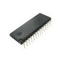
DG538ADJ Vishay, DG538ADJ Datasheet - Page 13

DG538ADJ
Manufacturer Part Number
DG538ADJ
Description
Analog Multiplexer Single 8:1 28-Pin PDIP
Manufacturer
Vishay
Type
Analog Multiplexerr
Specifications of DG538ADJ
Multiplexer Configuration
Single 8:1
Number Of Inputs
8
Number Of Outputs
2
Number Of Channels
1
Package Type
PDIP
Power Supply Requirement
Single/Dual
Single Supply Voltage (min)
10V
Single Supply Voltage (typ)
12/15V
Single Supply Voltage (max)
18V
Dual Supply Voltage (min)
±10V
Dual Supply Voltage (typ)
±12V
Dual Supply Voltage (max)
±15V
Power Dissipation
625mW
Mounting
Through Hole
Pin Count
28
Operating Temp Range
-40C to 85C
Operating Temperature Classification
Industrial
Package
28PDIP
Maximum On Resistance
90@15V@-3V Ohm
Maximum Propagation Delay Bus To Bus
300@15V|300@-3V ns
Maximum High Level Output Current
40 mA
Multiplexer Architecture
8:1
Number Of Channels Per Chip
1
Maximum Turn-off Time
175@15V@-3V ns
Maximum Turn-on Time
300@15V@-3V ns
Power Supply Type
Single|Dual
Lead Free Status / Rohs Status
Not Compliant
Available stocks
Company
Part Number
Manufacturer
Quantity
Price
Part Number:
DG538ADJ
Manufacturer:
INTERSIL
Quantity:
20 000
Document Number: 70069
S-05734—Rev. G, 29-Jan-02
+5 V
V
RS
EN
A
A
A
+15 V
FIGURE 11. On State Input Capacitance
L
0
1
2
8/4
4/2
V+
or
Notes:
a.
b.
a.
GND
Both V+ and V– must have decoupling capacitors mounted as close as possible to the device pins. Typical decoup-
ling capacitors would be 10-mF tantalum bead in parallel with 100-nF ceramic disc.
Production tested with V+ = 15 V and V– = –3 V.
For V
D
I/O WR
A
L
= 5 V "10%, 0.8- or 2-V TTL compatibility is maintained over the entire operating voltage range.
–5.5
–3 V
D
V–
S
S
S
S
A1
An
B1
Bn
B
–5
Allowable Operating Voltage
–4
Negative Supply Voltage
V– (Volts)
(Note b)
–3
Area
or Equivalent
Impedance
HP4192A
Analyzer
Meter
–2
FIGURE 13.
+5 V
–1
V
RS
8/4 or 4/2
+15 V
GND
L
V+
0
FIGURE 12. Off State Input/Output Capacitance
22
21
20
19
18
17
16
15
14
13
12
11
10
I/O WR
Positive Supply Voltage
EN
V+ (Volts)
–3 V
S
S
S
S
V–
D
D
A1
A2
B1
B2
A
B
Vishay Siliconix
DG534A/538A
or Equivalent
Impedance
HP4192A
Analyzer
Meter
www.vishay.com
13


