A-SERIAL PROGRAM USB ADP Fujitsu Semiconductor America Inc, A-SERIAL PROGRAM USB ADP Datasheet
A-SERIAL PROGRAM USB ADP
Specifications of A-SERIAL PROGRAM USB ADP


Related parts for A-SERIAL PROGRAM USB ADP


A-SERIAL PROGRAM USB ADP Summary of contents
Page 1
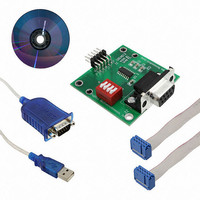
... PC Serial Programming Adapter Cable for Fujitsu Flash Microcontroller- F²MC-16LX/FR Family Fujitsu Microelectronics America, Inc. USER GUIDE P/N: 1 ...
Page 2
... Revision History Revision # Date 1.0 03.25.2001 2.0 08.21.2003 3.0 04.11.2005 4.0 01.30.2006 Comment New Document Added devices in the Table Added devices in the Table and modified the layout of the document. Added USB to serial cable description 2 ...
Page 3
... Fujitsu Microelectronics America Inc San Jose ´s sole discretion, either return of the purchase price and the license fee, or replacement of the Product or parts thereof, if the Product is returned to Fujitsu Microelectronics America Inc San Jose in original packing and without further defects resulting from the customer’ ...
Page 4
... Overview This document is intended to give an idea about in circuit serial programming of the Fujitsu F family flash Microcontroller using an adapter cable. This method allows the user to program the microcontroller directly on the target system without additional RS232 circuit. This solution saves some space on the target board and minimizes the cost of the system required for serial programming ...
Page 5
... RTS and CTS line should be connected together. The DTR should be connected to the DSR line in order to avoid the communication error. The RD line has to be connected to the SOT, and the TD line has to be connected to the SIN via the RS232 driver to the microcontroller for voltage level conversion. ...
Page 6
... Figure 2: Flash Adapter schematic Diagram 1 SIN SW1 100nf 3 MD0 C3 4 GND 100nf 5 MD2 6 SOT 7 Pxx 8 Pyy 9 +Vcc 100nf C4 100nf To Target Board 1 C1+ 3 C1- 4 C2+ 5 C2- 11 T1IN T1OUT 14 10 T2IN T2OUT 7 12 R1OUT R1IN 13 +5V 9 R2OUT R2IN DTR 5 GND 6 DSR 7 RTS 8 CTS ...
Page 7
... The pin outs for the header is shown in the figure 4, and table1). 3. Connect '9 pin serial cable' or 'USB to serial cable' on one side to the adapter cable (J2) and other side to the PC. 4. Set all DIP switches SW1 (MD0, MD2, Pxx, and Pyy) position to ON. Pxx aand Pyy pins are corresponds to the pins listed in the Appendix A and B for starting pin for programming ...
Page 8
... Requirement on Customer Target Board In order to connect the adapter cable to the target board required to have the 10-pin standard IDC header on the target board with the connection shown below. Figure 3 shows the connections from the microcontroller to header. For detail pin out refer to Appendix A/B. ...
Page 9
... Table 1: Pin Description of Header on the Target Board Pin No. Description 1 SIN/ MD0 4 GND 5 MD2 6 SOT/SO 7 Pxx 8 Pyy 9 +Vcc 10 NC Details Connected to the SIN of the Microcontroller. Refer table-2 shown below. Connected to the MD0 pin of the MCU Ground of the Target board and MCU Connected to the MD2 pin ...
Page 10
... Appendix A MCU Pins used for Flash asynchronous Programming in F2MC Family 10 ...
Page 11
... Microcontroller pins used for Serial Programming 11 ...
Page 12
... Microcontroller pins used for Serial Programming 12 ...
Page 13
... Appendix B MCU Pins used for Flash asynchronous Programming in FR Family 13 ...
Page 14
... Microcontroller pins used for Serial Programming Type MB91F109 MB91F133 MB91F233 MB91F264 MB91FV310/F312 MB91F353/F355 MB91F362/365/366/367/368/369 Serial Data Serial data Input pin output pin SI0/PF0/TRG0 SO0/PF1/TRG1 PI0/SIN1 P11/SOT1 P00/SIN0 PO1/SOT0 P20/SIN0 P21/SOT0 SI0 SO0 PH3/SI3 PH4/SO3 SIN0 SOT0 14 Starting pin for programming program ...