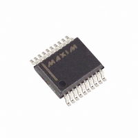
MAX349EAP+ Maxim Integrated Products, MAX349EAP+ Datasheet - Page 13

MAX349EAP+
Manufacturer Part Number
MAX349EAP+
Description
IC MULTIPLEXER 8X1 20SSOP
Manufacturer
Maxim Integrated Products
Type
Analog Multiplexerr
Datasheet
1.MAX350CPN.pdf
(20 pages)
Specifications of MAX349EAP+
Function
Multiplexer
Circuit
1 x 8:1
On-state Resistance
100 Ohm
Voltage Supply Source
Single, Dual Supply
Voltage - Supply, Single/dual (±)
2.7 V ~ 16 V, ±2.7 V ~ 8 V
Current - Supply
1µA
Operating Temperature
-40°C ~ 85°C
Mounting Type
Surface Mount
Package / Case
20-SSOP
Package
20SSOP
Maximum On Resistance
500@3V Ohm
Maximum Low Level Output Current
30 mA
Multiplexer Architecture
8:1
Maximum Turn-off Time
300@3.6V ns
Maximum Turn-on Time
600@3.6V ns
Power Supply Type
Single|Dual
Lead Free Status / RoHS Status
Lead free / RoHS Compliant
Note: NO and COM pins are identical and interchangeable. Either may be considered as an input or an output; signals pass equally
Figure 1. Timing Diagram
COM-OUT
DIP/SO
6–13
DIN
DOUT
14
15
16
17
18
SCLK
—
—
—
—
1
2
3
4
5
CS
well in either direction.
MAX349
6–9, 11–14
10, 15, 16
SSOP
17
18
19
20
—
—
—
—
1
2
3
4
5
______________________________________________________________________________________
PIN
8-Channel/Dual 4-Channel Multiplexers
DIP/SO
10–13
6–9
14
15
16
17
18
—
—
—
1
2
3
4
5
MAX350
t
CSS
t
DS
SSOP
11–14
10, 16
Serially Controlled, Low-Voltage,
6–9
—
—
15
17
18
19
20
1
2
3
4
5
t
DH
t
CH
NO0A–NO3A
NO3B–NO0B
NO0–NO7
COMA
COMB
RESET
NAME
DOUT
SCLK
COM
GND
N.C.
DIN
CS
V+
V-
t
DO
t
CL
Serial Clock Digital Input
Positive Analog Supply Voltage Input
Serial Data Digital Input
Ground. Connect to digital ground. (Analog signals have
no ground reference; they are limited to V+ and V-.)
Common Analog Switch (mux output)
Normally Open Analog Switch Inputs 0–7
Common Analog Switch “A” (mux output)
Normally Open Analog Switch “A” Inputs 0–3
Normally Open Analog Switch “B” Inputs 0–3
Common Analog Switch “B” (mux output)
No Connect, not internally connected.
Negative Analog Supply Voltage Input. Connect to GND
for single-supply operation.
Serial Data Digital Output. Output high is V+.
RESET Input. Connect to logic high (or V+) for normal operation.
Drive low to set all switches off and set internal shift registers to 0.
Chip-Select Digital Input (Figure 1)
FUNCTION
t
CSH2
Pin Description
t
t
ON
OFF
,
13


