7P.26.9.420.1020 FINDER, 7P.26.9.420.1020 Datasheet - Page 19
7P.26.9.420.1020
Manufacturer Part Number
7P.26.9.420.1020
Description
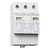
SURGE ARRESTER, PV TYPE, 420VDC
Manufacturer
FINDER
Datasheet
1.7P.20.9.350.0020.pdf
(20 pages)
Specifications of 7P.26.9.420.1020
Current Rating
100mA
Supply Voltage
420VDC
No. Of Poles
1
Mounting Type
DIN Rail
Rohs Compliant
Yes
Svhc
No SVHC (20-Jun-2011)


Protection against SPD’s short circuits is provided by the overcurrent
protective devices (fuses type gL/gG) recomended.
If the overcurrent protective devices F1 (which are part of the
installation) have a rating smaller than or equal to the maximum
recommended rating for the overcurrent protective devices F2 (back up
fuse), then F2 can be omitted.
If F1 > 160 A, then F2 = 160 A (F2min = 125 A only for SPD Type 2)
If F1 ≤ 160 A, then F2 can be omitted
The use of 125 A fuse gL/gG, instead of fuse rated 160 A gL/gG, as
short circuit overcurrent protection is permitted and does not
compromise the efficiency and the safety function of the SPD.
Coordination of SPD
Optimal protection from surges requires cascaded coordinated SPDs.
Coordination has the purpose of splitting the energy associated with
voltage across the SPDs and it is achieved by introducing an
impedance between the SPDs, or alternatively, by connecting them
using wires having the minimum length indicated in the figures
below, in order to use the impedance of its own conductor.
7P Series - Surge Protection Device (SPD)
PROTECTING PHOTOVOLTAIC (PV) SYSTEMS AGAINST
LIGHTNING
Photovoltaic systems are generally located external to a building and
can be subjected to the direct or indirect effects of lightning.
Whilst the installation of photovoltaic panels on the roof does not, in
itself, increase the risk of direct lightning, the only practical way to
protect against the effects of a direct lightning strike would be the use
of a lightning protection system (LPS).
The indirect effects of lightning can however, be mitigated by the
appropriate use of Surge Protection Devices (SPD). These indirect
effects occur when lightning strikes in proximity to the structure and where
magnetic induction creates an overvoltage in the conductors – a
danger to both people and equipment. In particular, the DC cables of
a PV system would be exposed to the high conducted and radiated
disturbances caused as a result of the lightning currents. In addition,
overvoltages in PV systems are not only of atmospheric origin. It is
also necessary to consider overvoltages due to switching on electrical
networks connected to them. These overvoltages can also damage both
the inverter and the PV panels, and this explains the need to protect the
inverter on both DC and AC sides.
Installation characteristics
[U
voltage and must be greater or equal to the maximum no-load voltage
of the PV system - depending on the configuration: earth free or mid
central earthing.
It is suggested that the maximum no-load voltage of the PV system is
calculated on the basis 1.2 x N x U
no-load voltage of the single PV module in standard conditions and
N is the number of modules connected in series in each array of the
PV system (TS 50539-12).
Earth free system
An earth free system installation, typical of smaller systems, is
characterized by the DC side floating, without connection to the
ground. U
poles. Class II photovoltaic panels are normally used in earth free
system. However, if Class I panels are used, their metallic frames have
to be earthed for safety reasons.
Figure 8: Earth free system installation
Mid central earthing
This system is used in larger installations, with high voltages: the
ground connection to the mid point reduces by half the maximum
voltage with respect to the ground. In this case U
voltage between the pole connected to the SPD and the ground.
Figure 9: Mid central earthing installation
OC STC
] PV voltage: corresponds to the SPD maximum operating
OC STC
refers to the voltage between positive and negative
OC(module)
, where U
OC(module)
OC STC
is the
is the
19
Related parts for 7P.26.9.420.1020
Image
Part Number
Description
Manufacturer
Datasheet
Request
R

Part Number:
Description:
JUMPER LINK, 20WAY
Manufacturer:
FINDER
Datasheet:


Part Number:
Description:
INTERFACE RELAY, SPDT-CO, 24VAC/DC
Manufacturer:
FINDER
Datasheet:
Part Number:
Description:
INTERFACE RELAY, SPDT-CO, 24VDC
Manufacturer:
FINDER
Datasheet:

Part Number:
Description:
RELAY, SCREW TERM, 6A, 12VAC/DC
Manufacturer:
FINDER
Datasheet:
Part Number:
Description:
RELAY, SCREW TERM, 6A, 48VAC/DC
Manufacturer:
FINDER
Datasheet:
Part Number:
Description:
RELAY, SCREW TERM, 6A, 125VAC/DC
Manufacturer:
FINDER
Datasheet:
Part Number:
Description:
RELAY, SCREW TERM, 6A, 240VAC/DC
Manufacturer:
FINDER
Datasheet:
Part Number:
Description:
RELAY, SCREW TERM, 6A, 6VDC
Manufacturer:
FINDER
Datasheet:
Part Number:
Description:
RELAY, SCREW TERM, 6A, 12VDC
Manufacturer:
FINDER
Datasheet:
Part Number:
Description:
RELAY, SCRW TER, DPDT, 8A, 24VAC/DC
Manufacturer:
FINDER
Datasheet:
Part Number:
Description:
RELAY, SCREW TERM, DPDT, 8A, 12VDC
Manufacturer:
FINDER
Datasheet:
Part Number:
Description:
RELAY, SCREW TERM, DPDT, 8A, 24VDC
Manufacturer:
FINDER
Datasheet:

Part Number:
Description:
RELAY, SCREWLESS, 6A, 24VDC
Manufacturer:
FINDER
Datasheet: