7P.20.1.000.9020 FINDER, 7P.20.1.000.9020 Datasheet - Page 18
7P.20.1.000.9020
Manufacturer Part Number
7P.20.1.000.9020
Description
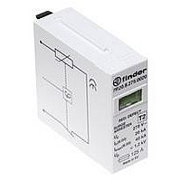
SPARK GAP MODULE
Manufacturer
FINDER
Datasheet
1.7P.20.9.350.0020.pdf
(20 pages)
Specifications of 7P.20.1.000.9020
Current Rating
100mA
Supply Voltage
420VDC
No. Of Poles
1
Mounting Type
DIN Rail
Rohs Compliant
Yes
Svhc
No SVHC (20-Jun-2011)


Rated values and marking common to all SPD
[U c ] Maximum continuous operating voltage: Under this voltage the SPD
is guaranteed to appear as an “open switch”. This voltage is normally
at least equal to the nominal supply voltage (U
Finder SPD, U c is specified as 275 V.
[U p ] Voltage protection level: This is the highest voltage level seen across
the SPD during its intervention. For example, for Finder SPD Type 2, this
means that a 4kV overvoltage would be limited by the SPD to a
maximum 1.2 kV. Consequently, electronic devices such as PC, TV,
stereo, etc. are protected - as their own internal protection will handle
overvoltages up to 1.5 kV.
To better understand this concept; imagine that the SPD is a switch in
series a low resistance. In the case of an overvoltage the switch
closes and all the current goes through the resistance. According to
Ohm’s law the voltage developed across the resistance will be this
resistance x the current (V = R x I), and will be limited to < U p .
Figure 4: Overvoltage limiting
Short circuit proof: A further characteristic, not normally marked on the
product but important for its correct installation, is the Short circuit proof
at maximum overcurrent protection. This is the maximum short-circuit
current that the SPD is able to withstand when it is installed with
additional maximum overcurrent protection - such as a fuse rated in
accordance with the value stated under the SPD specification.
Consequentely the maximum prospective short-circuit current of the
system at the point of installation of the SPD must not exceed this value.
Rated vaules and marking of SPD Type 1
SPD Type 1 must be connected upstream the system, at the point of
delivery of power energy. SPD protects building and people from the
risk of direct lightning (fire and death) and are characterized by:
[I imp 10/350] Impulse current: I imp corresponds to the peak value of
a 10/350 μs current impulse waveform. This waveform represents a
direct lightning strike and is used in tests to prove the performance of
SPD type 1 devices.
Figure 5: 10/350 μs current waveform
Comparison of the waveforms in figures 5 and 6 shows the much
higher energy content controlled by the type 1 SPD.
18
N
) + 10%. For the
7P Series - Surge Protection Device (SPD)
[I n 8/20] Nominal discharge current: The peak current (and waveform
shape) through the SPD under conditions prescribed by EN 62305 to
represent the surge current as a consequence of a lightning strike to the
electric supply line.
I (peak)
Figure 6: 8/20 μs current waveform
Rated values and marking of SPD Type 2
SPD Type 2 devices are designed to remove all the overvoltage from
supply circuits that are not likely to be directly hit by lightning. SPD Type
2 are connected downstream SPD Type 1 or SPD Type 1+2, (minimum
distance 1 m) and they protect machine and tools connected to the grind
and reduce the risk of economic loss.
SPD Type 2 are characterized by:
[I n 8/20] Nominal discharge current: The peak current (and waveform
shape) through the SPD under conditions prescribed by EN 62305 to
represent the surge current as a consequence of a lightning strike to the
electric supply line.
[I max 8/20] Maximum discharge current: Peak value of the highest
current of a 8/20μs waveform that an SPD can discharge at least once
without breaking.
Rated values and marking of SPD Type 3
SPD type 3 devices are used to protect the end user from overvoltage.
They may be installed in supply networks where SDP types 1 and/or
2 already exist. They can be installed in fixed or mobile sockets and
have the following characteristic parameters.
U oc : test voltage. This is the peak value of the no load voltage of the
combined test-generator; this has a waveform of 1.2/50 μs
(figure 7) and can supply at the same time current with waveform 8/20
μs (figure 6).
Figure 7: 1.2/50 μs voltage waveform
Suggestion for the connection
The correct connection of SPD requires a shortest as possible
connection to the equipotential local bar, to which are connected PE
cables of the equipment to be protected. From the equipotential
local bar there is a connection to the EBB. The phase wiring remains
appropriate to the load.
Related parts for 7P.20.1.000.9020
Image
Part Number
Description
Manufacturer
Datasheet
Request
R

Part Number:
Description:
JUMPER LINK, 20WAY
Manufacturer:
FINDER
Datasheet:


Part Number:
Description:
INTERFACE RELAY, SPDT-CO, 24VAC/DC
Manufacturer:
FINDER
Datasheet:
Part Number:
Description:
INTERFACE RELAY, SPDT-CO, 24VDC
Manufacturer:
FINDER
Datasheet:

Part Number:
Description:
RELAY, SCREW TERM, 6A, 12VAC/DC
Manufacturer:
FINDER
Datasheet:
Part Number:
Description:
RELAY, SCREW TERM, 6A, 48VAC/DC
Manufacturer:
FINDER
Datasheet:
Part Number:
Description:
RELAY, SCREW TERM, 6A, 125VAC/DC
Manufacturer:
FINDER
Datasheet:
Part Number:
Description:
RELAY, SCREW TERM, 6A, 240VAC/DC
Manufacturer:
FINDER
Datasheet:
Part Number:
Description:
RELAY, SCREW TERM, 6A, 6VDC
Manufacturer:
FINDER
Datasheet:
Part Number:
Description:
RELAY, SCREW TERM, 6A, 12VDC
Manufacturer:
FINDER
Datasheet:
Part Number:
Description:
RELAY, SCRW TER, DPDT, 8A, 24VAC/DC
Manufacturer:
FINDER
Datasheet:
Part Number:
Description:
RELAY, SCREW TERM, DPDT, 8A, 12VDC
Manufacturer:
FINDER
Datasheet:
Part Number:
Description:
RELAY, SCREW TERM, DPDT, 8A, 24VDC
Manufacturer:
FINDER
Datasheet:

Part Number:
Description:
RELAY, SCREWLESS, 6A, 24VDC
Manufacturer:
FINDER
Datasheet: