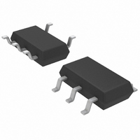
LTC1694CS5#TRMPBF Linear Technology, LTC1694CS5#TRMPBF Datasheet - Page 6

LTC1694CS5#TRMPBF
Manufacturer Part Number
LTC1694CS5#TRMPBF
Description
IC ACCEL SMBUS DUAL TSOT23-5
Manufacturer
Linear Technology
Datasheet
1.LTC1694CS5TRMPBF.pdf
(8 pages)
Specifications of LTC1694CS5#TRMPBF
Applications
Data Transport
Interface
SMBus (2-Wire/I²C)
Voltage - Supply
2.7 V ~ 6 V
Package / Case
TSOT-23-5, TSOT-5, TSOP-5
Mounting Type
Surface Mount
Operating Temperature (min)
0C
Operating Temperature Classification
Commercial
Operating Temperature (max)
70C
Rad Hardened
No
Ic Interface Type
I2C, SMBus
Supply Voltage Range
2.7V To 6V
Operating Temperature Range
0°C To +70°C
Digital Ic Case Style
SOT-23
No. Of Pins
5
Msl
MSL 1 - Unlimited
Slew Rate
0.5V/µs
Rohs Compliant
Yes
Bandwidth
100kHz
Lead Free Status / RoHS Status
Lead free / RoHS Compliant
Other names
LTC1694CS5#TRMPBFTR
Available stocks
Company
Part Number
Manufacturer
Quantity
Price
APPLICATIO S I FOR ATIO
LTC1694
R
I
Fall Time
Fall time is a function of the SMBus capacitance, R
and the pull-up current. Figure 3 shows the maximum
allowed (R
requirement of 300ns with a 50ns safety margin.
The maximum value of R
ments, can also be calculated by rearranging equation 6.
Given below are some equations that are useful for calcu-
lating rise and fall time and for selecting the value of R
Initial Slew Rate
The initial slew rate, SR, of the Bus is determined by:
C
I
(125 A).
SR must be greater than SR
detector threshold (0.5V/ s max) in order to activate the
2.2mA boosted pull-up current. This limits the maximum
SMBus capacitance.
6
PULL-UP(MAX)
PULL-UP(MIN)
BUS
ON(MAX)
SR = I
Figure 3. Maximum Value of R
Capacitance for Meeting the SMBus t
is the total capacitance of the SMBus line.
PULL-UP(MIN)
:
1.4
1.2
1.0
0.8
0.6
0.4
0.2
S
0
0
+ R
: The maximum LTC1694 low pull-up cur-
is the LTC1694 minimum pull-up current
V
The maximum on resistance of the open-
drain driver
rent is 350 A
CC
ON
= 5V
100
) based on the Intel SMBus fall time
U
BUS CAPACITANCE (pF)
/C
BUS
200
U
S
, based on fall time require-
THRES
S
300
+ R
, the LTC1694 slew rate
ON
W
f(MAX)
400
as a Function of Bus
1694 F03
Requirement
500
U
S
, R
(2)
ON
S
.
SMBus Rise Time
Rise time of an SMBus line is derived using equations 3,
4 and 5.
if V
I
typ).
For an SMBus system, V
For the LTC1694, typically V
I
C
SMBus Fall Time
Fall time of an SMBus line is derived using equation 6.
where R
Rise and fall time calculation for an I
follows.
I
Rise time of an I
Fall time of the I
For an I
and V
For an I
0.3 • V
C
PULL-UP(B)
PULL-UP
2
BUS
BUS
C Bus Rise and Fall Time
t
[V
t
t
C
t
f
t
t
[V
r
1
IL(MAX)
2
r
f
= R
BUS
IL(MAX)
= R
= t
= (V
= (V
= (V
IL(MAX)
is the total capacitance of the SMBus line.
is the total capacitance of the I
IH(MIN)
CC
1
L
2
2
/I
L
L
C system with V
C system with fixed input levels, V
= 275 A.
IH(MIN)
+ t
PULL-UP
• C
THRES
IH(MIN)
and V
• C
is the sum of R
– 0.15 > V
is the LTC1694 boosted pull-up current (2.2mA
2
– 0.15 – (R
BUS
– (R
BUS
= 3V.
IH(MIN)
– V
• ln{[(0.9 • V
– V
2
+ 0.15 – V
2
• ln{[V
L
C line can be derived using equation 8.
C line is derived using equation 7.
• I
IL(MAX)
IL(MAX)
PULL-UP
THRES
= 0.7 • V
L
IH(MIN)
IL(MAX)
CC
• I
S
) • C
+ 0.15) •
, then t
THRES
PULL-UP(LOW)
related input levels, V
and R
)]}
CC
– (R
= 0.8V and V
BUS
) – (R
CC
) • C
ON
.
1
THRES
/I
L
= 0 s.
PULL-UP(B)
(see Figure 2).
2
• I
L
2
BUS
C line.
C system is as
• I
PULL-UP
)]}
/I
PULL-UP(LOW)
PULL-UP(B)
= 0.65V and
IL(MAX)
IH(MIN)
)]/
IL(MAX)
= 2.1V.
= 1.5V
1694fa
)]/
(3)
(4)
(5)
(6)
(7)
(8)
=


