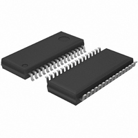
BU21050FS-E2 Rohm Semiconductor, BU21050FS-E2 Datasheet - Page 6

BU21050FS-E2
Manufacturer Part Number
BU21050FS-E2
Description
IC CAP SENSOR SWITCH 8CH 32-SSOP
Manufacturer
Rohm Semiconductor
Type
Capacitive Switchr
Specifications of BU21050FS-E2
Package / Case
32-SSOP
Input Type
Logic
Output Type
Logic
Interface
Port
Current - Supply
550µA
Mounting Type
Surface Mount
Supply Current
550µA
Supply Voltage Range
4.5V To 5.5V
Sensor Case Style
SSOP
No. Of Pins
32
Operating Temperature Range
-40°C To +85°C
Svhc
No SVHC (18-Jun-2010)
Base
RoHS Compliant
Supply Voltage
5 V
Dimensions
13.6 mm L x 7.8 mm W x 1.8 mm H
Power Dissipation
760 mW
Temperature Range
- 55 C to + 125 C
Termination Style
SMD/SMT
Base Number
21050
Rohs Compliant
Yes
Lead Free Status / RoHS Status
Lead free / RoHS Compliant
Lead Free Status / RoHS Status
Lead free / RoHS Compliant
Other names
BU21050FS-E2TR
●Setting method
●Operation Mode
●Power Supply ON Sequence
© 2009 ROHM Co., Ltd. All rights reserved.
BU21050FS
www.rohm.com
【Filter selection】
1)Please for the first time in a minimum gain.
2)THOFF = 0V, and, THON 1/2VDD voltage as a guideline for whether or not to switch ON, and gain selection to
This IC has several modes, called detection mode, calibration mode, and shut-down mode. Each modeis described as follow
【Detection Mode】
【Calibration Mode】
【Shutdown Mode】
This IC has two power input pins AVDD and DVDD. Power ON sequence must be whether set DVDD firstor set the two at
one time. Since internal reset circuit is monitoring AVDD, wrong power ON sequencemay cause initialization error.
The noise filter effect can be selected If “Strong” is selected, noise will get down, but the reaction time will be longer.
please the rough.
Note: ON gain to a minimum, you gain more precision amended to increase the impact too, so please take note.
This is normal operation mode of this IC. In this mode, IC detects the sensor capacitance continually.
Under detection mode when no operation has been detected for sometime, Sensor offset calibration will be done.
And the interval between each calibration is fixed
Detection mode and Calibration mode are switched automatically.
When SDN pin is set to “L”, IC will be shut-down and all internal circuits will stop working. IC will work again
when SDN pin is set to “H”.
Sensor ON threshold
FILTER = ” L ” : filter effect → under
delay time → small
FILTER =”L”: filter effect
6/7
delay time
→
→
strong
big
Switch detect time
Technical Note
2009.04 - Rev.B


