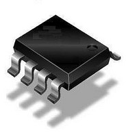
QT115A-ISG Atmel, QT115A-ISG Datasheet - Page 52

QT115A-ISG
Manufacturer Part Number
QT115A-ISG
Description
IC TOUCH SENSOR PROX 8SOIC
Manufacturer
Atmel
Datasheet
1.AT42QT1040-MMH.pdf
(72 pages)
Specifications of QT115A-ISG
Input Type
*
Output Type
*
Interface
*
Current - Supply
*
Mounting Type
Surface Mount
Operating Supply Voltage
3 V to 5 V
Maximum Operating Temperature
+ 85 C
Mounting Style
SMD/SMT
Package / Case
SO-8
Minimum Operating Temperature
- 40 C
Lead Free Status / RoHS Status
Lead free / RoHS Compliant
Package / Case
-
Lead Free Status / Rohs Status
Details
10620D–AT42–04/09
Self-capacitance One-dimensional Sensors
5.4
5.4.1
5-6
Typical Resistively Interpolated Method
Medium/Large Slider Or Wheel
This sensor uses more than three electrodes in total, with only three of them directly connected to the
sensor chip. The rest of the electrodes are connected using resistors to provide an electrical
interpolating effect.
This arrangement can be useful for constructing large sliders out of simple rectangular segments (see
Figure
segments are not only simple to draw, but they also work better when the taper angle of the more
conventional design yields unfeasibly sharp and slender structures.
The resistors can be physical components soldered to the PCB, preferably on the non touch side. They
can also be printed (for example, carbon), in which case they can be located on the touch side of the
PCB.
It is also possible to make such a slider from a completely resistive carbon strip, with the connection
points making a full width contact across the strip and the two ends joined as already described (that is,
the continuous equivalent of the “lumped” example shown in
Note that typically, extending a slider too far in length leads to poor SNR and also worsens any problems
caused by the hand shadow effect (see
Figure 5-6.
The sensor design for medium/large wheels is essentially the same as that for sliders, but with the
electrode segments wrapped into a complete ring (see
medium/large slider, this design does not attempt to introduce any dead bands, thus allowing continuous
operation across the 0°–360° boundary.
5-6), or large wheels out of simple wedge-shaped segments
Resistors R1 and R2 form a “dead band” at the each end to stop end wrap-around.
Make them approximately 5 percent of Rtotal to achieve a 5 percent band at each end.
Note that not all Atmel slider chips need these.
Medium/Large Slider (Resistively Interpolated)
R1
Rtotal typically 100 kW
Channel 0
Channel 2
Rtotal typically 100 kW
Section 5.2.3 “Hand Shadow Effect” on page
6–8 mm
Channel 1
Figure 5-7 on page
0.1–0.5 mm Gap
Rtotal typically 100 kW
Figure
5-6).
(Figure 5-7 on page
5-7). Unlike the design for the
Touch Sensors Design Guide
R2
5-2).
5 15 mm
–
5-7); these


